The Dynaco (or Dynakit) Stereo 70 (also known as the ST-70) vacuum tube amplifier was one of the most popular tube amps of its time. Retailing for $99.99 in kit form ($129.99 in factory-wired form), roughly 300,000 of them were produced from 1959 to the late 1970s. If you have acquired a Stereo 70 in unknown condition, there are several things you should do before trying it out. Unless it was working when you acquired it, you shouldn't assume that it is working, and there are several parts that should be replaced even if it you think it works. Do not just plug it in and turn it on, or there could be catastrophic results. WARNING: some parts of this amplifier use voltages in excess of 400V. If you do not feel comfortable working on a device which employs such high voltages, have someone who is repair it for you. Do not work on the amplifier while it is plugged in. Even while turned off, high voltages can be found near the power cord. Before doing work near the filter capacitors, make sure they are discharged by shorting them with an insulated wire or screwdriver. Also, make sure that the solder joints you make are good. If not, they could cause problems. If you do not know how to solder, take the amplifier to someone who does.
Preventative Maintenance
There are some components you must replace before powering the amp up. These parts are the ones most likely to cause tube failure. These components are:
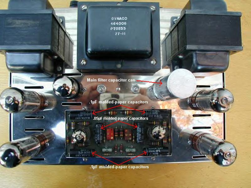
1. Molded-paper capacitors: These are the large, black tubular devices on the circuit board. These are prone to leak current over time. They should be replaced with modern equivalents such as mylar-film, Sprague "Orange Drops", or other high-voltage (400V or larger) capacitors of the same or similar values. Be very careful when working on the circuit board, or you could pull up one of the traces. For a picture of the top of the chassis showing where the capacitors are, click the thumbnail below.
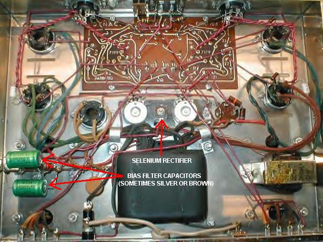
2. Selenium rectifier: This is the small square metal device bolted to the middle of the underside of the chassis. These build up resistance over time, and can fail dramatically, taking tubes and other valuable parts with it when they do. Replace it with a 1N4004 or better silicon diode, being sure to have the correct polarity (wire from the transformer to the cathode (striped end), the other wire to the anode (non-striped end)). The best thing to do is unwire and remove the selenium rectifier, install a terminal strip in its place, and solder the silicon diode to the terminal strip. The selenium rectifier may be put back in if its bolt is used to mount the terminal strip, but leave it disconnected.
3. Bias filter capacitors: these are the two brown or silver tubular devices near the rear of the underside of the chassis. Like the molded-paper capacitors, these are known to leak current over time, and this may lead to the tubes getting damaged. Replace them with modern electrolytic capacitors of similar value (47-100µF@50-160V). Note that electrolytic capacitors have a positive side and a negative side. Many modern electrolytic capacitors have arrows pointing to the negative side of the capacitor, or a plus sign (+) near the positive side. If polarities are not noted, these capacitors could explode! For a picture of the underside of the chassis showing where the selenium rectifier and the bias filter capacitors are, click the thumbnail below.
4. Main filter capacitors: This is the tall metal can on top of the chassis, across from the 5AR4 rectifier tube (see the first thumbnail above for an example). These aren't always bad, but considering the fact that the newest original ST-70s are approaching their 40th birthday, and the average lifespan of an electrolytic capacitor is around 20-30 years (sometimes less), they're well overdue for replacement. If you desire, you can test the four sections of the existing can capacitor for shorts or opens by measuring between each of the inner lugs and the chassis (shorts measured across the outer lugs is normal) using a good analog or digital ohmmeter able to measure at least one megohm of resistance. If any of these sections test as open (infinite ohms) or shorted (0 ohms), you will need to replace the entire can capacitor as outlined below. One or more open sections often will cause a 120Hz hum in the speakers; if one or more sections have shorted, this could take out the rectifier tube and/or power transformer! Even if these capacitor sections test perfectly fine and seem to be working now, they could fail at any time, so it's a good idea to just go ahead and replace the capacitor can.
The simplest option is to install a replacement capacitor can, as are available from Dynakit Parts and Antique Electronic Supply, among others. Make sure that the sections of the new capacitor can are rated for at least 525V, and that it is connected the same way as the old one was, paying particular attention to the 30µF section (identified by a semi-circle symbol on the bottom of the can). Upgrade can capacitors are available which have larger value capacitors inside; if using one of these, make sure that the section connected to the rectifier tube is no larger than 40µF. In any case, when replacing the can capacitor, it may be a good idea to replace the 6.8k and 22k ohm resistors connected between the other sections of the capacitor can; use metal film resistors rated for at least 1 watt.
The cheapest option would be to disconnect the wires from the lugs on the capacitor can, and mount replacement electrolytic capacitors to a terminal strip under the chassis. It's best to use values as close to the originals as possible (three 22µF capacitors and a 33µF capacitor, all rated for at least 525V), though it may be possible to use larger capacitors in some of the sections (the initial 30µF section should be made no larger than 40µF, since it's connected directly to the rectifier tube). Make sure that the leads of the new capacitors and the lugs of the terminal strip don't come into contact with the chassis or any other parts. Some companies offer capacitor boards which install under or on top of the chassis; these sometimes also have bias supply parts mounted to them. These often have uprated parts, which may change the sound of the amplifier, and may also be more expensive than the other two options.
Final Preparations
Inspect the underside of the amplifier. If you see any wax underneath the transformer area, this may indicate that one of the transformers was stressed in the past. Inspect the power cord. If it is cracked or brittle, replace it with a modern one. It is a good idea to check the transformer leads for opens or shorts using an ohmmeter or continuity tester, especially if they look to have been stressed sometime in the past. Also, make sure the fuse is of the correct value (3A slow-blow type). If the fuse is of the correct rating but is blown, there may be a short-circuit somewhere in the power supply section. If you see any components that don't look right, replace them. A schematic can be found here.
Also, look for burnt components. If any of the resistors (the small tubular color-coded devices on the circuit board and under the chassis) look charred, test them with an ohmmeter; the color code can be found on other websites. If any of them are found to be outside their tolerance range, replace them with resistors of similar ratings. Most of the resistors are rated 1/2 or 1 watt; be sure the resistors you use are of the correct wattage. Suitable resistors and capacitors can be found at Antique Electronic Supply. Note that after 30-40 years, the bias potentiometers most likely are dirty on the inside. Clean the bias pots with a good contact cleaner (such as DeOxit, which is available from Antique Electronic Supply and other sources) by spraying directly into the pot through access holes in the back, under the chassis. Rotate several times to wipe the contacts. Clean up excess cleaner with a rag and allow to dry before powering up. Another thing that should be cleaned with contact cleaner are the tube sockets. Spray contact cleaner inside every hole of the sockets and wipe the excess cleaner off the chassis with a rag. . Also, make sure that the individual pin holders are gripping the pins well. This can be verified from underneath. Be sure to wait a while after applying contact cleaner to any contact before turning the amp on. Finally, be sure to check your work afterwards to make sure that there aren't any faulty connections, cold solder joints, loose blobs of solder, or pieces of cut wire present. These sorts of things could cause all sorts of problems down the line.
The Big Moment
If all of these things seem to check out, you can make some preliminary tests. It is recommended that this should be done with a device that allows the voltage supplied to the amplifier to be increased slowly. This is usually done with an autotransformer (also known as a "Variac"), but if you do not have one, you can use a dim-bulb tester.
The first test: This test will determine if the power transformer will work, and if you have installed the bias supply parts correctly. Remove all the tubes from the amplifier, and put them in a safe place where they won't be prone to falling off the bench and breaking. If you are using a Variac turn its dial to 0, plug the amplifier into its outlet, and plug it in. If you want to use a dim-bulb tester, build it from the instructions on the webpage. If you're brave and don't want to use one of these devices, plug it in and be prepared to unplug it quickly if something goes wrong. If all seems well, turn it on. If powering it up with a Variac, slowly turn the dial towards 120; if using the dim-bulb tester, follow the instructions on the page. If you hear any sizzling or see any smoke, TURN IT OFF! Look for the source of the smoke. If it's the power transformer, you will need to purchase a new one (available from Triode Electronics and Dynakit Parts, among others). If it's the bias section, make sure you installed all the parts with the correct polarity, or the filter caps may blow up.
The second test: This critical test will determine if all the tubes work, and will not apply high voltages to the parts. Insert all the tubes except the 5AR4 rectifier, and then turn the amp on (using the Variac or dim-bulb tester might not be needed at this stage, since it has been established that the transformer and bias section works). If all the tubes light up, turn the amp off. Double-check all the parts that you have replaced, set the bias potentiometers (the two controls on top of the chassis) to the center of their rotations. During this test, you may want to check the voltages at the tube filament pins. This may be accomplished by testing the voltage at pins 2 and 7 of any of the 6CA7/EL34 tubes, or at pins 1 and 2 of the preamp power takeoff socket on the front. If the voltage measured is in the range of 6.1-6.4V AC, the tubes will last a long time. However, if the voltage measured is higher than this range, the line voltage in your household may be too high. One solution would be to put a 20 ohm, 20 watt power resistor in series with each of the filament windings, and measure the filament voltage. If it is still higher than the range above, increase the resistance. However, if it is lower, reduce the resistance.
The third test: Now, we are going to apply all voltages to the amplifier. If you are using a Variac or dim-bulb tester, repeat the steps for the first test. Connect a pair of speakers to the output jacks (noting correct impedance and polarity). Put in the 5AR4, and turn the amp on. If you notice any sparks, sizzling, smoke, loud humming or glowing tube plates, TURN IT OFF! If 120Hz humming can be heard from the speakers, then one or more of the main filter capacitors (the large metal can on top of the chassis) have gone bad, and need to be replaced (see above). If the loud humming is coming from one of the transformers, it could be bad. If the tubes fail to light, the fuse may have blown. A blown fuse may indicate a shorted component (rectifier tube, filter capacitor or transformer). Glowing tube plates, especially in the output tubes, may indicate a problem in the bias section or that the tubes are mismatched or bad. If all is well, listen for a hissing sound from the speakers; this indicates that the amplifier may be working. It may be a good idea to check the filament voltage again during this test. Putting the rectifier in introduces more load on the amplifier, and may lower filament voltage slightly. If the voltages measured are lower than 6.1V, reduce the size of the dropping resistor that may have been installed previously so that the filament voltages will be between 6.1 and 6.4V. Please note that a dropping resistor circuit shows working voltage(s) only under load, filament voltages cannot be measured completely accurately until all tubes are installed, and all working voltages are achieved. Please also note that there are two separate filament windings, one per channel. This means that if there is any imbalance between electrically identical channels, then there is a fault in some component within the amp, or in the power-transformer itself, or in one or more of the tubes.
Setting Bias/Replacing Tubes
Bias is a negative voltage applied to the tubes which keeps them under control. In many amplifiers this is hard to set, but Dynaco simplified the process. To test the bias, place the positive lead of a multimeter (set to DC volts) in the Biaset slot of either of the two eight-pin sockets on the front, touch the other lead to the chassis, and adjust the bias potentiometers until you measure 1.56V DC. I recommend using an old analog multimeter such as the Simpson 260 for this purpose, but a digital multimeter may be used if the decimal place can be set to show hundredths or thousandths of a volt. Bias readings should always be done with the amplifier at idle (passing no signal). Set the bias shortly after startup, and again after around a half an hour (to allow the tubes to warm up fully). Once the bias is set, it usually doesn't have to be set again unless tubes or parts are changed. Make sure that the multimeter being used is accurate. An easy way to make sure of the correct voltage is to use a carbon-zinc D cell battery as a reference. Test the voltage coming from the D battery, then set the Biaset voltage to the same level. Do the same for the other socket, and adjust both until you read about 1.56V from both sockets. It may take some time to balance the two sides, so be patient.
If you cannot get one side to bias to 1.56V, one or more of the EL34 tubes in that side may be weak. Try to replace both tubes in that side with a matched pair of EL34s, 6CA7s or E34Ls. It is preferable that the tubes used are matched, or problems may occur (glowing plates, distortion, etc.). I recommend using JJ/Tesla E34Ls or Electro-Harmonix EL34EHs, matched pairs or quads of which can be bought from Triode Electronics, Tube Depot, and many other sources. If you would rather not use new-production tubes, NOS (new-old stock) 6CA7/EL34 tubes of American or European manufacture can still be bought, but the price may be astronomical ($60-100+ per tube). Note: Be wary of Chinese tubes, especially 5AR4/GZ34s. Some may work fine, while others may fail dramatically, taking out valuable parts with them! Also, note that tubes do not fail due to age alone. If a tube is old, it does not automatically need to be replaced. Only replace a set of tubes if one of them is definitely bad. If you wish to do further testing on the amplifier while replacement tubes are being shipped, a set of lower cost, but less powerful 6L6WGB/5881s or 6L6GCs can be substituted temporarily if you set the bias to 1.56V. 7199s are no longer being made, though some old and recent production tubes are still available. Dynakit Parts sells adapters which allow for 6GH8As or 6U8As to be used in their place. Also, many replacement driver boards use alternative tube types.
A Note On Modification
Some people recommend changing the circuit board before doing anything else. Personally, I think that you should give the stock driver board a decent listen (after having replaced the parts outlined above) before doing any major modifications. There is a reason they were built as they were, and can sound very nice with a stock circuit. If the driver board in your ST-70 is damaged, new driver boards using the stock circuit (sometimes modified for 6GH8s or somesuch, since 7199s are getting hard to find) are available from many sources. Two other modifications suggested by some restorers are replacing of the input/output jacks with gold-plated ones, and removal of the stereo/mono switch from the circuit. I generally do not recommend replacing these parts, as it complicates things, and changes the general shape of the amplifier. If you wish to perform such mods, go right ahead; I tend to see them as unnecessary.
Final Testing
If everything checks out, connect a preamplifier with a volume control to the input jacks on the front of the Stereo 70, and connect a source to the preamplifier (a portable CD player or other portable music player works in a pinch, but watch the volume control!). Adjust the volume of the preamplifier to a minimum, start the source, and adjust the volume control to a preferred level. If the sound is distorted, check the source. If the source is not to blame, there may be a problem in the bias section. If a 60Hz hum is present, try another source. If a hum is still present, there may be a ground problem in the amplifier itself. If all seems well, sit back and enjoy the music!
A final note: Many of the tips in this article also apply to the restoration of other Dynaco tube amplifiers, such as the Mark III, Mark IV, and ST-35. Get a copy of the manual for your amplifier, note the similarities and differences, and have at it!
Parts Resources
Triode Electronics
Antique Electronic Supply
Tube Depot
Dynakit Parts
Site Navigation:
Back to the tube page!
Back to the main page!