Nixie Clock Version 4
Return to Home
Return to Projects
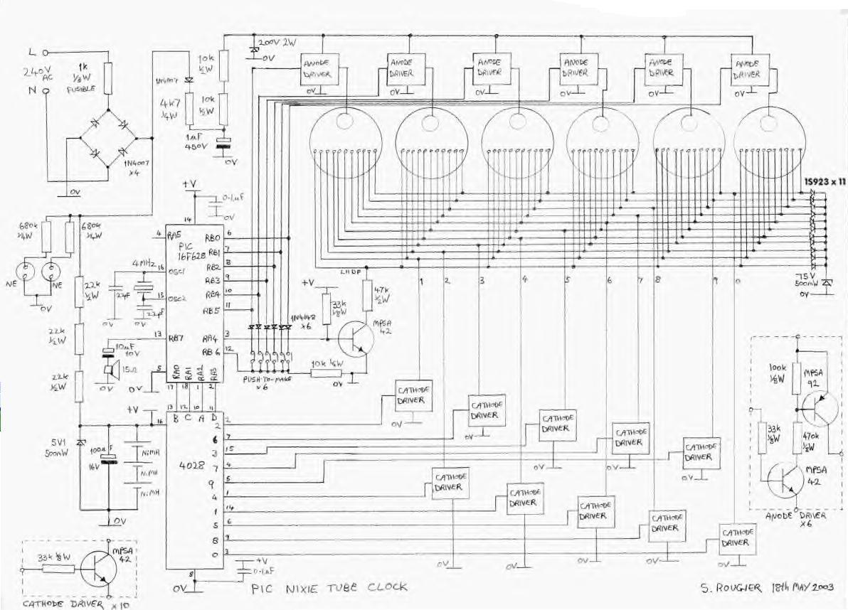
A copy of the original schematic and source codes from Steve Rogier are provided here:
Schematic
ASM source code
HEX source code - ready to program on a 16F628
Please note that the source code here was slightly modified to display the zero digit in the 10 hours during the single-digit hours like 09:00 instead of (blank) 9:00. I did not use all the features of this clock such as the alarm. Unfortunately, this clock has a very strange way with the switches for setting the time and changing modes from the default 24 hours to 12 hours. It took me a while playing around with the switches until I could find out what effects each switch had because the details were not quite clear on Steve's website. Below is a table that Steve provided on how to use the switches:
| Mode | Button 1 | Button 2 | Button 3 | Button 4 | Button 5 | Button 6 |
| Normal | Next mode | Alarm on/off | Stop Alarm | Snooze | Stop Alarm | Stop Alarm |
| Set Time | Next mode | Hours +1 | Mins +1 | Reset secs | Return to Normal mode | |
| Set Alarm | Next mode | Alarm hours +1 | Alarm mins +1 | Snooze +1 | Return to Normal mode | |
| Adjustment | Next mode | Down | Up | 12/24 hour | Return to Normal mode | |
| Alarm Tone | Next mode | Down | Up | Fade Rate + 1 | ||
| Display Test | Next mode |
Since I did not want to use all the features of the program, I only used 4 buttons for changing mode, hours, minutes, and to reset the seconds. According to my notes, the buttons did not seem to correlate to the suggested pinout ordering in the schematic. My notes indicate that I figured out Button 1 = RB3, Button 2 = RB1, Button 3 = RB4, and Button 5 = RB0.
I built a case using two layers of cedar wood glued together with the bottom piece cut out. The case was cut and sanded down to appear like a big wooden speedbump, then the six holes were cut out for the nixies. Since I did not have sockets for the nixies, I carefully soldered the wires directly on the pins of the nixies themselves. This is a very delicate job as the heat can crack the glass and render the nixie useless.
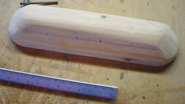
The case before drilling and staining.
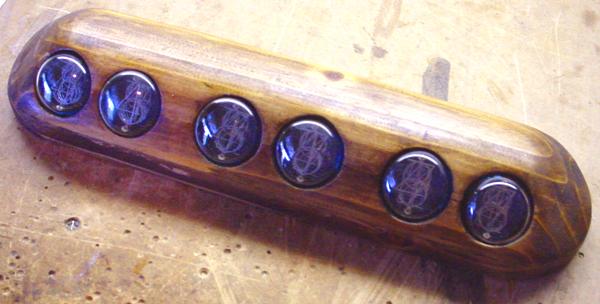
The case after staining and the nixies glued in place.
The inner walls of the holes were painted black beforehand.
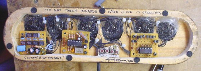
The completed innards of the clock.
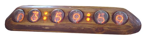
The completed Version 4 Nixie Clock
This picture was taken at the instant the time rolled over to 4:00:00 so these digits began to fade in.
Back to Top