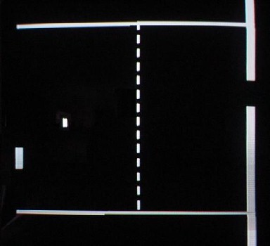
Analog TV Pong Game
Return to Home
Return to Projects
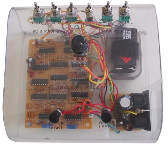
This entire Analog TV Pong Game is built using only ten CD4001 quad NOR and three CD4011 quad NAND ICs. The gates are used in "analog mode" because the design relies on many RC circuits for delay and pulse shaping with gates reacting to analog signals to produce digital signals that are combined to produce a composite video signal for a TV. This analog PONG game was based on an article featured in Electronics Australia, May 1976, which can be found at this link: http://www.pong-story.com/eaus0576.htm, but you may download a easily printable PDF of the article.
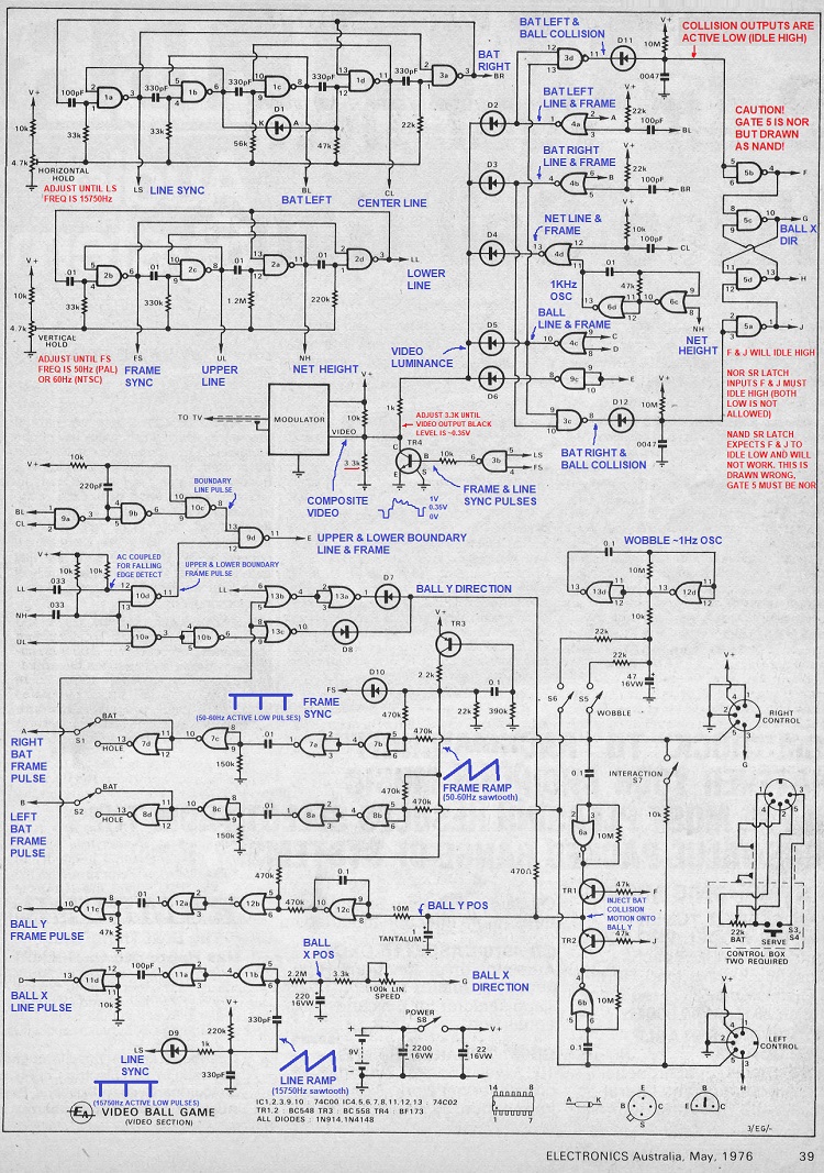
The original design used obsolete CMOS 74C00 quad NOR and 74C02 quad NAND ICs that are most similar to the CD4001 and CD4011 respectively. I did not use the PCB featured in the article because the pinouts of the CD4000-series ICs are slightly different from the original 74C-series ICs so a new PCB design would have to be done anyway. Although the circuit may seem quite complicated to start from scratch, I idenified each section to build one at a time. I hand-wired the connections, checking rigorously as I went on, and was fortunate to only have one minor short that was fixed easily. The following schematic image has my annotated notes, and here is a higher resolution printable PDF.
When I originally built the circuit as a teenager in circa 2005, I had problems with the ball horizontal circuit because the ball would slide to the left paddle and stay there without bouncing or just slide right through. I was able to track down the problem to the SR latch IC 5 that controls the ball's horizontal position having a problem triggering. I had implemented a poor band-aid to sort of bypass the top and bottom IC5 gates that produced signals F and J and had a working albeit very flaky solution for the ball X direction control. But all the other circuits worked as intended. I could not get the output composite video signal to be recognized by a TV as a valid NTSC signal and ended up using a RF modulator salvaged from a VCR to output to channel 3 and let the TV recover the video signal itself. I do not know if it is possible to fine tune the video output to be recognized as NTSC, but be mindful that because the entire design operates in "analog mode" the delays and frequencies will drift a bit over time and many modern TVs are intolerant of NTSC instabilities.
Fast forward 18 years later in 2023, an interested visitor to this project page inquired about some of my build issues so I dusted off my old TV pong project and fired it up. Unsurprisingly, the game still produced video for a TV but the ball died again. With a fresh set of eyes and more EE background, I realized IC5 was drawn incorrectly as a NAND when it is supposed to be a NOR. The ball collison detection logic is active low and creates a low pulse when the paddle/bat and ball pulses collide and then there's an inverter to square up the RC stretched pulse, so the outputs F and J will idle high. A NAND SR latch only works with SR inputs idling low, but a NOR SR latch works with SR inputs idling high. Also I realized now that the left/right serve buttons will force a short on the SR latch outputs G and H to flip their state to change the ball's horizontal X direction. This is not a great idea because the outputs of the NOR gates will be stressed momentarily and could eventually get damaged. A better solution is to put in some 50 ohm resistors immediately on the outputs of the gates producing signals G and H, so when either serve button is pressed to short either G or H, current flow is limited by the 50 ohms to reduce stress on the gate outputs. After remedying those issues, the latch functioned as expected but the ball was still non-functional. The final culprit was a dead 220uF electrolytic capacitor that stores the ball X position voltage. Apparently the capacitor failed shorted and would not charge. After replacing the capacitor, the console was fully resurrected and functioned much more reliably than it did when I originally built it 18 years ago.
Information on the reference points in the schematic:
Horizontal Oscillator Section:
| Reference Point | Name | Purpose |
| BL | Bat Left | Pulse that positions the left paddle/bat X location |
| BR | Bat Right | Pulse that positions the right paddle/bat X location |
| CL | Center Line | Pulse that positions the dotted center line X location |
| LS | Line Sync | Pulse at the beginning of a horizontal line and should have a frequency of 15,750Hz for NTSC |
Vertical Oscillator Section:
| Reference Point | Name | Purpose |
| FS | Frame Sync | Pulse at the beginning of a vertical sweep and should have a frequency of 50Hz for PAL, 60Hz for NTSC |
| UL | Upper Line | Pulse that positions the upper boundary line Y location |
| LL | Lower Line | Pulse that positions the lower boundary line Y location |
| NH | Net Height | Wide pulse that is active between the upper and lower boundary Y locations for the net (dotted center line). |
Other Sections:
| Reference Point | Name | Purpose |
| A | Right paddle/bat or hole vertical frame Y location pulse | |
| B | Left paddle/bat or hole vertical frame Y location pulse | |
| C | Ball vertical frame Y location pulse | |
| D | Ball horizontal line X location pulse | |
| E | Composite upper boundary and lower boundary video. | |
| F | Enables TR1 to inject some vertical movement from right paddle/bat onto the ball during collision. | |
| G | Ball X direction that feeds into the ball X position RC circuit with speed control. Also could be force shorted by SERVE button to change direction. | |
| H | Inverse of ball X direction not used anywhere else other than to be force shorted by SERVE button. | |
| J | Enables TR2 to inject some vertical movement from left paddle/bat onto the ball during collison. | |
| V+ | 6Vdc source | This should be self-explainatory. |
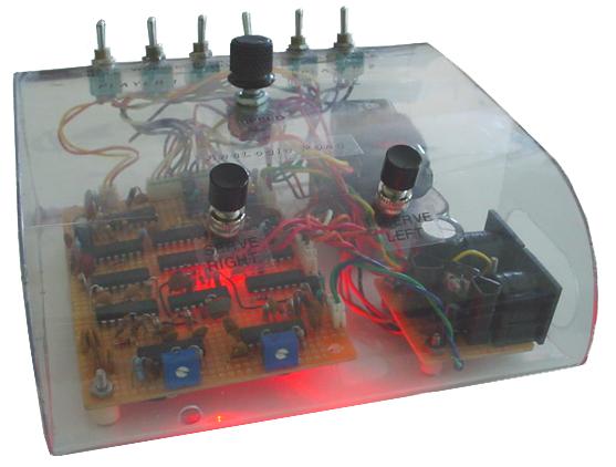
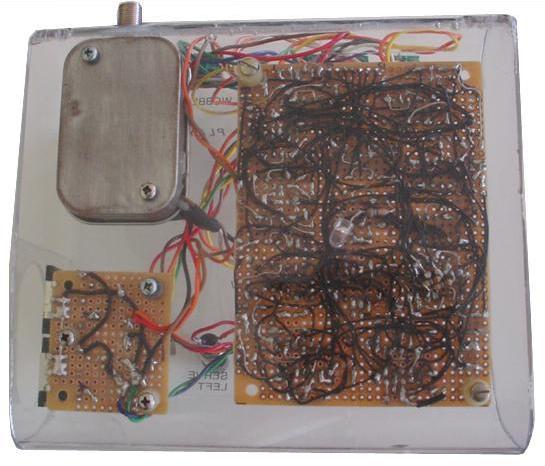
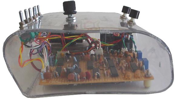
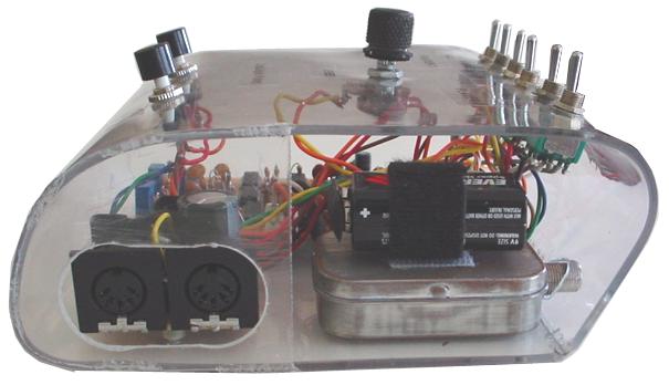
The case was built out of plexiglass that was heated up in an oven set to 500 degrees for a few minutes and then bent into shape. The sides of the case were made out of thin plexiglass attached to the main case by plastic welding using a soldering iron. There is a hole in front of the case for a small screwdriver to be used to adjust the vertical hold if the picture starts flipping.
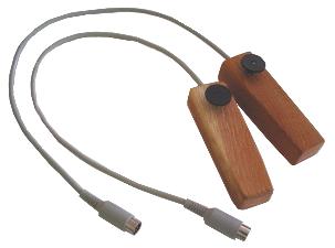
Homemade Paddle Controllers
Single Player
Two Players