Oscilloscope Clocks
Return to Home
Return to Projects
Version 1: The Altoids Scope Clock
This oscilloscope clock project uses a PIC 16F876 and a DAC to generate X and Y signals to draw a clock on the oscilloscope. The original circuit and software was designed by OZ2CPU, which can be found here: http://www.webx.dk/oz2cpu/clock-scope/scope.htm. The clock circuit was slightly modified to use a different DAC from Texas Instruments. The 60Hz signal was obtained from the AC side of a 12VAC (NOT DC) wall adapter and the current is limited with a 10K resistor. Below is the schematic of the minimal oscilloscope clock circuit:

At first I didn't bother building the entire oscilloscope from scratch because I had a handful of oscilloscopes sitting around. However, the only working oscilloscope I had with a Z axis input was the Tektronix 7704A, but experiments showed that the blanking signal from pin 26 of the PIC was not entirely necessary. The blanking is only used to supress any lines from appearing while the DAC quickly changes from a point to another point. It turns out that the vectors are drawn so quickly that there is almost nothing visible between points without the blanking signal. Omitting the use of the blanking signal makes this circuit more versatile for a wide range of oscilloscopes with simple X and Y inputs, including vacuum tube oscilloscopes! However, the graphics are stable and crisp with DC coupling to the oscilloscope. Most tube scopes use AC coupling, but if the deflection amplifiers are designed well then the graphics will look pretty good. The only downfall with AC coupling is a degree of image distortion and the image will drift around the CRT face, but the benefit of the drifting is a reduced risk of phosphor burn on the screen.
The two switches (SW1 and SW2) sets the time, but I'm not sure which switch does what so you'll have to find out. One switch will change the clock mode which includes Run, Hours Set, and Minutes Set. The other switch will change the digits for the time set modes. The HEX file for the program I used is here: scopeclock60hz.hex. Note that Thomas (OZ2CPU) wrote the clock program and did not provide the .ASM file. The 50Hz version can be found on his scope clock webpage (link provided above).
Note that the original crystal frequency specified by Thomas for the 60Hz version of the scope clock is 19MHz, but I had success using a 16MHz crystal for version 1 because that crystal was what I had on hand at the time. The 60Hz line frequency maintains the timekeeping, so crystal speed is not terribly important. However, a higher frequency crystal will provide better graphics refresh rates.
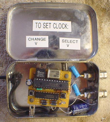
The oscilloscope clock was stuffed in a painted Altoids tin.
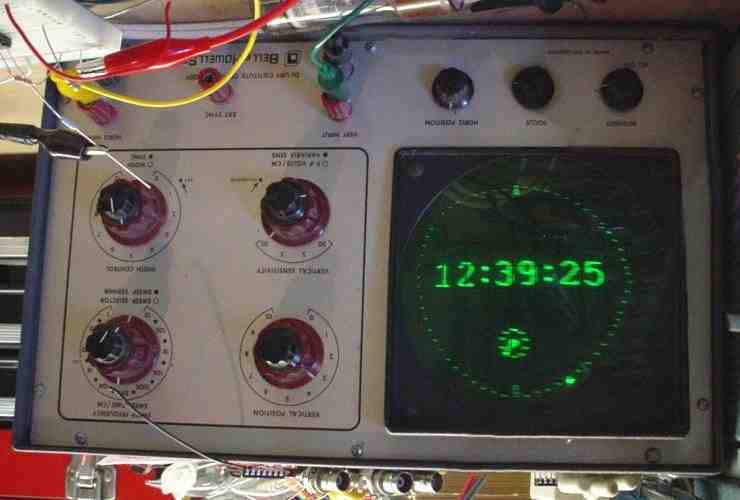
The oscilloscope clock on the Bell & Howell 34 tube oscilloscope. Note that I had to flip the photograph upside-down because the oscilloscope's Y plates are inverted.
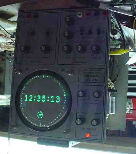
On the solid-state Bell & Howell. Here both the X and Y plates are inverted, so the photograph had to be flipped in both directions. I eventually reversed the X and Y plates to fix this problem.
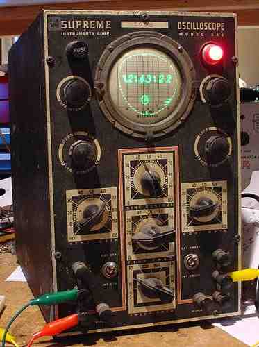
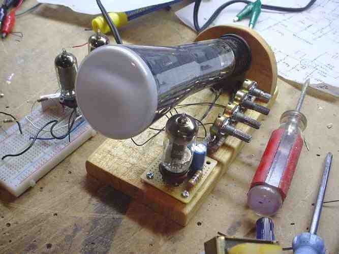
On the 1930's Supreme 546 tube oscilloscope. This is my favorite oscilloscope for demonstrating the clock because the image looks pretty good on the 3AP1 CRT.
Version 2: Tube Scope and Solid-State Clock
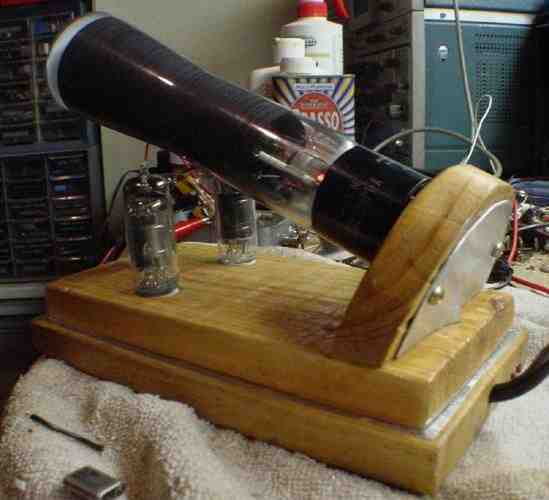
Later on I decided to make a dedicated scope clock and had a design for a simple three tube oscilloscope using a 6BC7 and a pair of 6AU6 tubes. It is nice to add a little of nostalgia to the clock by using an all-tube oscilloscope. I experimented with the circuit used in the Ultra-Simple Oscilloscope but avoided using a large power transformer by using the 6BC7 as a voltage tripler to provide the B+ supply. Moreover, a filament transformer for the tube filaments were also avoided by using a series circuit. Below is the schematic of the three tube XY oscilloscope using the 2AP1 CRT.
The 6BC7 tripler provides about 400VDC loaded, which is sufficient for the 2AP1 CRT and the 6AU6 deflection amplifiers. Later experimentation found that if the B+ was lowered to about 300VDC, the clock display on the CRT will grow larger but dimmer. However, with a lower B+ the oscilloscope needs a minute or two to warm up before the clock appears on the CRT. The series filaments are designed to respect the heater-to-cathode ratings of all the tubes. The 2AP1 can endure a heater-to-cathode rating up to -120VDC, the 6AU6's up to +/- 60VDC, and the 6BC7 up to 200V. However, the 6BC7 will have heater-to-cathode rating issues within the tube because it is used as a voltage tripler; one diode will supply 400VDC on the cathode while another diode only supplies 160VDC on the cathode. The filament in the 6BC7 is common to all the diodes, so the tube will have to tough it out.
For safety purposes, I would recommend a 0.25A fuse in series with the 56 ohm resistor that is across the 6BC7 filament and a 0.5A fuse in series with each of the 6AU6 filaments. This way if the 6BC7 or one of the 6AU6 tubes burn out, one of the fuses will blow and the whole filament string goes out. Without a fuse, if the 6BC7 burns out then the 56 ohm resistor will immediately see the 0.6A current flow and burn up. The same effect will happen to the 6AU6 filament if the other burns out. No fuse is needed in series with the 2AP1 because if its filament burns out then the whole string goes out.
Furthermore, the 2AP1, 6AU6 pair, and the 6BC7 filaments altogether add up to about 18V so the 11uF capacitor drops about 100 to 110 volts for 60Hz (50Hz will require a different capacitor value). Note that the 11uF capacitor must be non-polarized; an electroylic will explode due to the AC. The capacitor is slightly smaller than the calculated value so all the tube filaments run on slightly lower voltages which is good for the long term. The 56 ohm resistor in parallel with the 6BC7 filament should be about 40 ohms, but the resistance was increased so the 6BC7 filament would run hotter than the other tubes to supply more current for the B+ supply.
Why a 11uF capacitor instead of a resistor? The 2AP1 has a 6V 0.6A filament, the 6AU6's have 6V 0.3A which is why they are in parallel to add up to 0.6A, and the 6BC7 has a 6V 0.45A filament so the 56 ohm resistor takes care of the remaining 0.15A so the whole string draws 0.6A. However, the voltages add up to 18V so a drop of about 110 volts is needed. If a resistor was used to drop 110 volts at 0.6A, V = IR will give a value of about 180 ohms. However, resistors disspate power so P = IR = 0.6*110 = 66 watts! The benefits of using a capacitor in AC circuits is that they provide impediance and acts like a "resistor." To calculate the capacitance C, we know that f = 60Hz and Xc = R = 180, so C = 1/(2 pi f Xc) = 14.7uF but I use 11uF so the filaments don't run hot.
I noticed that the clock face would grow larger when the B+ was reduced, and then later learned that the easiest way to adjust B+ voltage was to adjust the 4.7K 1/2W resistor. Increasing this resistor in value will lower the B+ and make the picture larger, and decreasing the resistor will have the opposite effect. Note that as the resistor increases above 4.7K, the wattage increases rapidly. 10K will have to be at least several watts and 30K is around 12 watts. Another easier way is to omit the 4.7K resistor and connect pin 1 of the 6CB7 to ground. On the other hand, the brightness of the picture suffers from the lower B+.
The scope clock circuit had a few changes made to suit the tube oscilloscope. Below is the slightly modified schematic:
Note that there are 220uF electroylic coupling capacitors from the DAC to the deflection amplifiers. This provides a degree of isolation between the tube oscilloscope and the DAC. The PIC and DAC draw about 11mA which is too much of a load on the 6BC7 power supply; the 6BC7 can only manage about 12mA per diode. I used another diode, resistor, and capacitors but it took up too much space so I experimented with the idea of using a cheap little cell phone charger. The charger has a very compact switching power supply that is well capable of supplying about 6 volt at 11 to 12mA. It was stuffed in the last remaining space in the scope clock. The pictures below will help convey the idea of how cramped the space was undereath the oscilloscope clock.
Lastly, the tube deflection amplifiers are simple and not perfect. The clock is AC coupled to the amplifiers so there is some distortion and image drifting. However, the drifting actually helps prevent phosphor burn on the screen.
The tube oscilloscope before I decided to move the guts undereath and turn it into a scope clock.
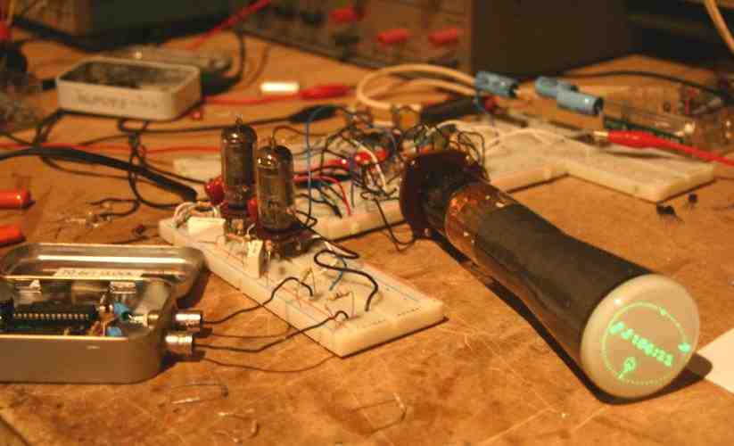
Early experiment with the circuitry for the scope clock.
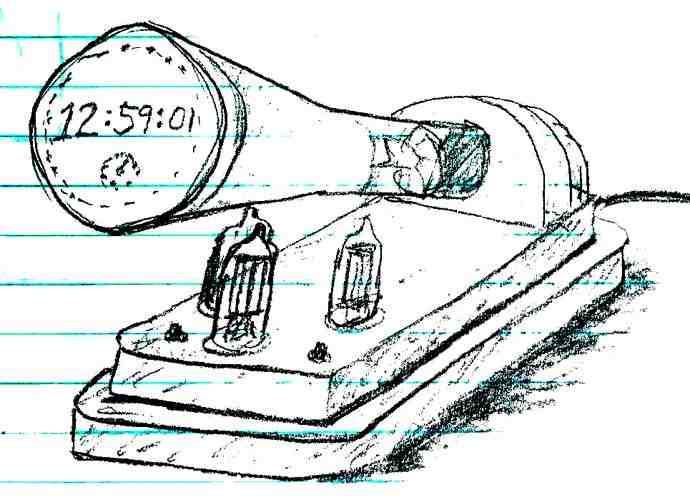
My rendering of the scope clock before it was fully built.
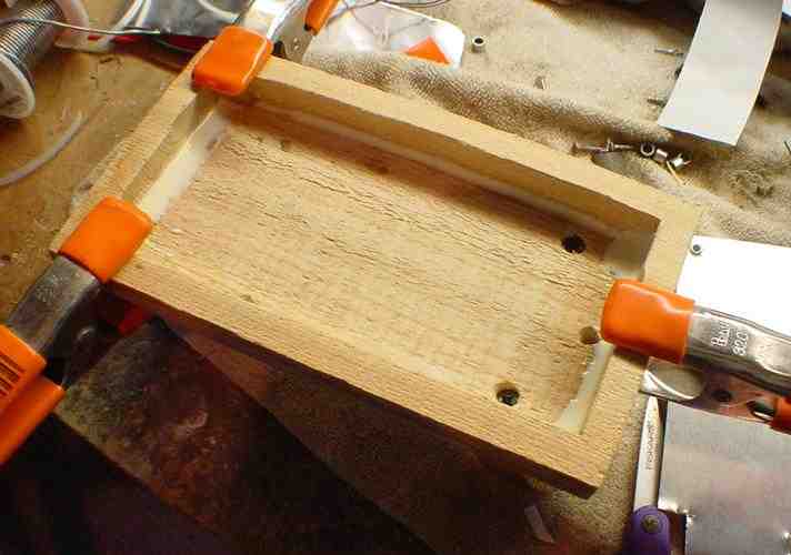
A second layer of wood with the inside area cut out was added to the base of the existing tube oscilloscope to house the electronics.
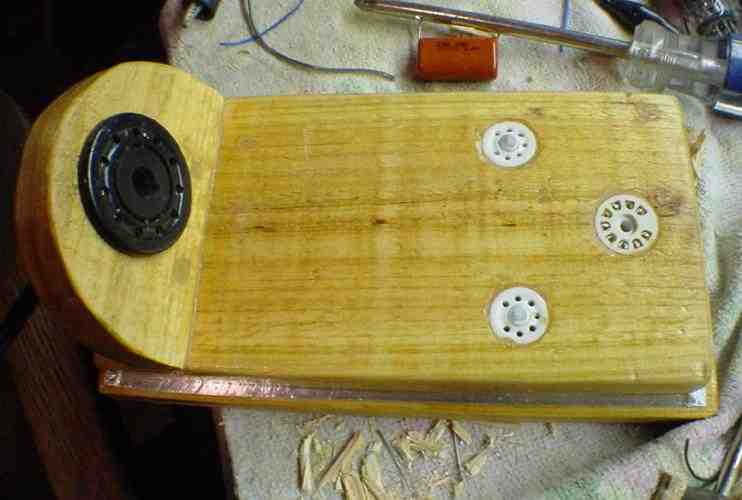
The top view of the clock with the tube sockets in place. The sockets are held in place by soldering the pins to small nails inside the case.
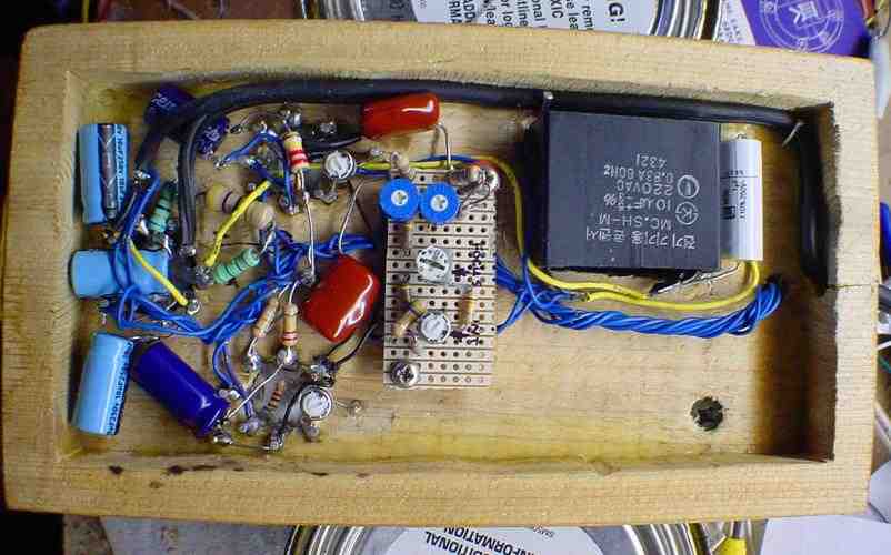
The innards with the tube oscilloscope circuitry completed. The clock circuit will go in the lower right area. The big black capacitor in the upper right of the photo is a 10uF capacitor with a 1uF capacitor (white tublar body) next to it in parallel for the tube filament circuit.
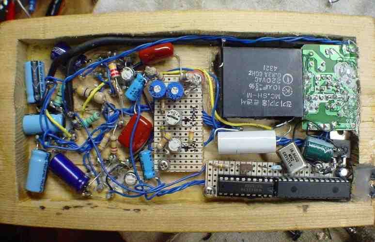
The innards of the completed scope clock. The board in the upper right is the cell phone charger supply for the clock. Pretty much every millimeter of the space undereath was used up.
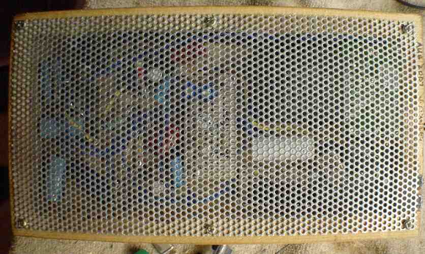
The bottom was covered with a metal mesh grille to protect the innards.
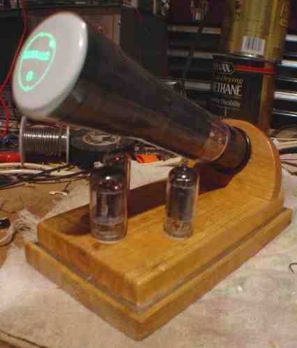
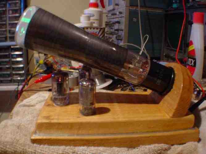
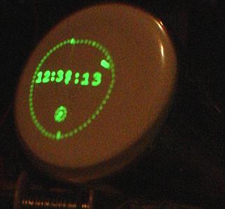
Close-up of the CRT display.
Version 3: Solid-State Scope and the Dutchtronix Clock
I received the excellent Dutchtronix Scope Clock kit to try out on the tube scope (version 2). You can obtain a kit here: http://www.dutchtronix.com/ScopeClock.htm.
The quality of the Dutchtronix clock graphics on the tube scope was rather disappointing because of the large distortion caused by the 6AU6 amplifiers. The amplifiers were built around the OZ2CPU scope clock that had simpler graphics. To avoid making adjustments and changes, I decided to build a whole new scope clock using simple solid-state components instead. Below is the schematic of the first version.
Please note that this version 3 design has been superceded by the solid-state version of the Ultra-Simple Oscilloscope. I have received many emails that expressed interest in the version 3 design. Version 3 was designed to be very simple with low parts count, but it is not easy to use and often does not work correctly at first. Please refer to the other webpage that details the better design. Furthermore, you can buy the Catahoula Technologies Oscilloscope CRT Driver PCB to help you get started.
The high voltage power supply is simply two voltage doublers that produce approximately +320V and -320V for a total potential of about 650V. I used a 3BP1 CRT, which works well with this voltage but the circuit should be compatable with many other 2" and 3" CRTs. I have no guarantees as I have not tested other CRTs, but if you use a different CRT that works well then let me know. Lastly, the high voltage supply is not isolated from mains so please use an isolation transformer if possible. A basic isolation transformer can be built using two 120V-to-12V transformers back to back with the 12V connected between the two transformers. The low voltage supply uses a transformer that provides 4-6V power to the CRT filament (rated 6V 0.6A) and 15 to 25 volts to be rectified and reduced to provide +5V and -5V for the clock and deflection amplifiers. The -5V supply is not critical and can vary up to -10V or so. The Dutchtronix clock requires regulated 5V so a 5-volt regulator such as the 7805 is strongly recommended.
When the circuit is first built, I would recommend leaving the Dutchtronix clock disconnected to check the voltages on the supplies. If all is well, then adjust the INTEN pot all the way towards the -320V for maximum brightness. Center the POS and SIZE pots and a dot should appear on the CRT face. Adjust FOCUS to sharpen the dot and ASTIG to make the dot as round as possible. After these steps are completed, the clock can be hooked up to the +5V supply and the outputs to the X INPUT and Y INPUT. Readjust the pots until the picture fills the CRT face and the quality is best.
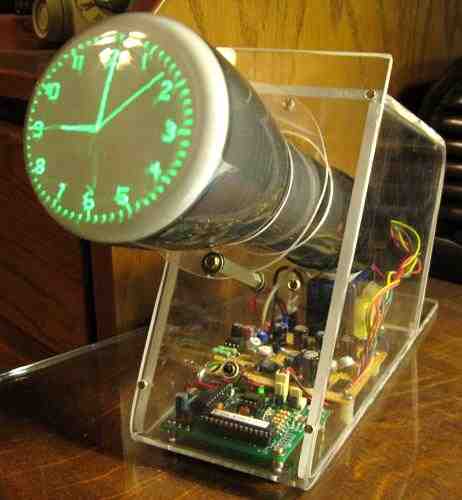
The circuit was built around the Dutchtronix scope clock kit. The graphics quality is ok and has slight distortion and some visible retrace lines. The 2.2K resistors on the inputs of the TL082 dual op-amps help linearize the output of the DAC of the clock, but these resistors can be removed to increase input impedance. The scope works reasonably well for the full clock with the digital numeric display turned off. The menu is readable albeit not perfect. I do not recommend making centering adjustments to the scope by using the calibration screen because the clock display has slightly different DC offset that will shift the picture off-center due to the 47uF coupling capacitors. Lastly, if the picture is flipped on one or both axes then simply reverse the connections on the deflection plates. The SIZE pot will adjust the size of the picture, but it also affects the positioning so the POS pot is used to recenter the picture.
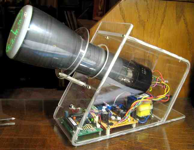
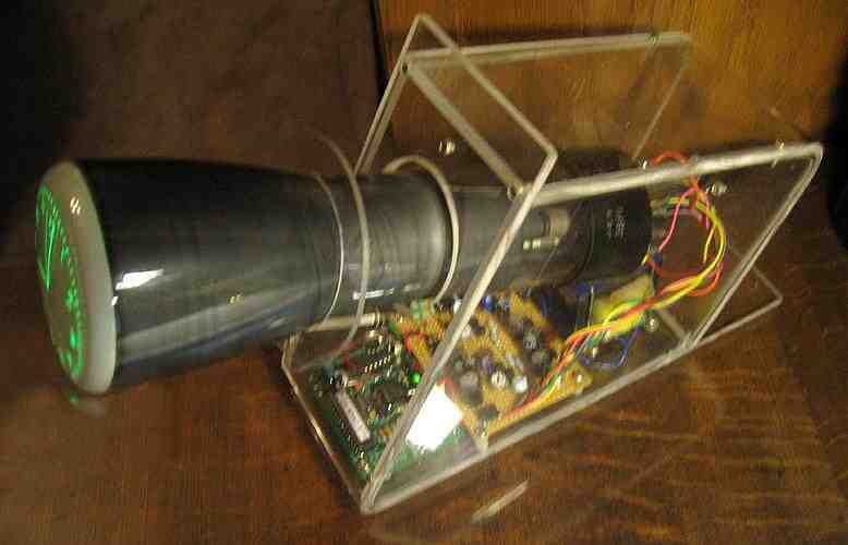
The clock innards were housed in a plexiglass cabinet that I made myself. A table saw was used to cut the striaght lines on the pieces. A heat gun was used for bending the front and rear pieces. The edges were filed and sanded down to fit, and then all the pieces were screwed together. My initial plan was to locate the CRT further in the cabinet but the magnetic field from the transformer caused the picture to "swim" so the CRT had to be located a bit further out. As a result, I added a plexiglass ring to hold the CRT in place and this adds an interesting touch to the overall appearance.
Back to Top