Old Fashioned Strobe
Return to Home
Return to Projects
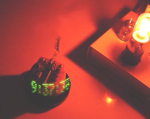
I found a how-to article online about building your own strobe using the 631-P1 strobotron in a July 1957 issue of Popular Electronics. Below are copies of the article; credits for the photocopies goes to Modern Mechanix.

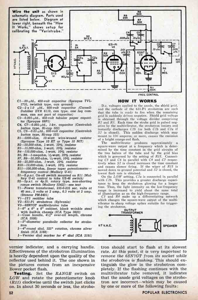
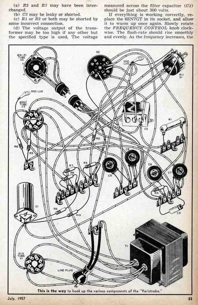
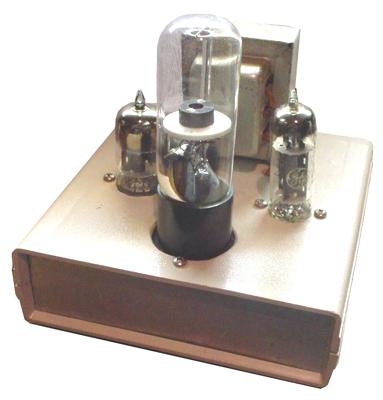
I noticed several mistakes in this article, especially on the schematic in page 2 and the wiring diagrams in page 3. The plans say that the transformer is 235-0-235, so in the schematic the winding where both ends connect to the plates of the 5Y3 rectifier should have a center tap that goes to ground. Otherwise, I can't imagine how their strobe worked without any 300VDC+ supply unless perhaps the grounded case of the transformer is connected to the center tap. In the wiring diagram on page 3, you will notice missing ground connections. Note the capacitor in the diagram is simply floating and connected at only one terminal. It should be pointed out that the capacitor case, ground lugs on the terminal strips, and other ground lugs are all connected because they are mounted on a metal chassis but it is not obvious.
I found a small transformer that supplies 6V and approximately 350VCT. Instead of using the center tap on the transformer which would only provide about 200VDC at most, I used a half-wave power supply circuit and left the center tap floating. One end of the 350VCT winding is grounded and the other end goes to the plates of the rectifier tube. I used a 6X4 miniature rectifier tube and wired both plates together to boost the current capability of the rectifier. I chose the 6X4 over the 5Y3 for a few reasons: it is a smaller 7-pin miniature rectifier tube (the 5Y3 is a larger 8-pin octal rectifier tube), and the 6X4 has a cathode while the 5Y3 does not. The cathode on the 6X4 allows me to wire the filaments of the rectifier and the multivibrator tube together, rather than having a transformer with an independent filament supply for the rectifier and another for the multivibrator. Note that this is necessary if you use the 5Y3 because the 5Y3 lacks a cathode so its filament acts like the cathode. As a result, the filament of the 5Y3 will supply the 300V source and if other tube filaments are wired to the same filament supply, those tubes' filaments will have a 300V potential. In this case the 6SN7 has its cathodes grounded and has a maximum filament-to-cathode rating of 90 volts. The 300V potential on the filament towards a grounded cathode would most likely ruin the tube. In short, using a rectifier tube without a cathode requires its own independent filament supply, and the 6X4 I chose has a cathode so the independent filament supply is not necessary.
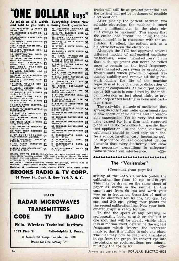
Instead of a 6SN7, I used a smaller 9-pin miniature tube equilavent, the 12AV7. Although many might think the 12AV7 needs a 12-volt supply for the filament, there is a center tap on the 12-volt filament so the filament can be powered with 6 volts. Aside from the two different tube choices, the design followed most of the information in the article. Below is the schematic of my old-fashioned strobe:

I built the strobe using a plastic enclosure case as the chassis. The strobe works pretty nicely, but obviously not as bright as a xenon strobe. The speed control varies the speed from about 5 cps (cycles per second) to 60 cps.
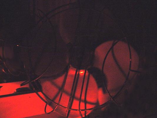
The strobe is not solely used for fun special effects. I experimented with the strobe on some moving objects. The first object I experimented with was a vintage Artic Aire fan. By adjusting the strobe frequency, I managed to get the rotating blades to appear still. My strobe successfully achieved this effect easily at around 15cps and 30cps. Below is a picture of the running fan with the strobe.
Also I took a picture of my propeller clock in operation using the strobe. It is obvious the propeller clock is running otherwise the camera would have not been able to capture the "illusion" of the digits in mid-air.