TV To Scope Converter
Return to Home
Return to Projects
Version 1: Simple Solid-State Converter
This project takes after the VGA-to-Scope converter by using composite video rather than VGA signals to create a display on an oscilloscope. The circuitry in the VGA-to-Scope converter has been greatly simplified; op-amp buffers and inverters were eliminated. The continuous current supply to charge up the capacitor linearly (the 3906 PNP transistor and associated resistors) was replaced with a simple 1Meg pot from 5V to charge up the capacitor, albeit creating a nonlinear sawtooth. When the pot is set just right, the capacitor will charge up at the correct rate and the trigger signal causes the 555 to discharge the capacitor for synchronization. Below is the schematic.


This converter is not as robust as the VGA-to-Scope converter so every time the circuit is powered up, the oscillators probably need readjustingso consider the 1Meg pots to be vertical and horizontal hold controls.
More information on the theory of how the circuit works or tricks with video can be found on the VGA-to-Scope converter page.
I don't have any pictures of the converter because I built it on a breadboard and disassembled it soon after some screenshots were taken.
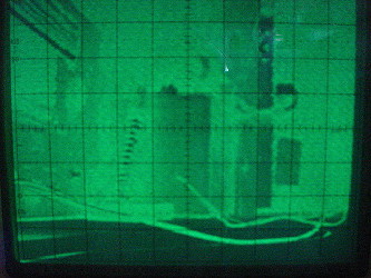
A view of my workbench (notice the soldering iron and the plugs)
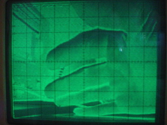
A view of my hand
Version 2: Improved Solid-State Converter
Among the improvements on version 1 includes the use of the 2N3906 and associated resistors for improved linearity of the sawtooth output. More importantly, a loop is introduced in the circuit from the output to the trigger input to allow the 555 timers to operate in astable (free running) mode. The advantage is that a raster will be present in the absence of a video signal so one does not have to worry about all the precautions with the oscilloscope before and after using the converter. Below is a schematic of the slightly revised converter.
Version 3: Tube TV-Scope Converter
Of course a simple converter can be done with tubes and has been done plenty times in the past when "hollow-state" was the only choice. I was inspired to build a converter after a fellow hobbyist created a converter based on a simple tube TV monitor schematic I had in the temporary folder. The circuit minus the CRT circuitry is presented below.
Sadly, pulling off the sync signals from the video is no simple feat. In the schematic above, the sync separator tube does not fully separate the sync from the video, but rather it attenuates the video sufficiently for the oscillators to lock onto the sync pulses. Another issue is the oscillators are not sensitive to weak and noisy sync signals so picture stability is rather marginal. A rather curious modification for the vertical oscillator is to use a neon bulb in a relaxation oscillator. Below is a schematic of a circuit that explores this idea.
For improved stability, a dedicated sync separator is needed. However, there is no hollow-state LM1881 to come to the rescue. Sync separation has to be done the old fashioned way. Below is a schematic of a more robust converter with improved picture stability.
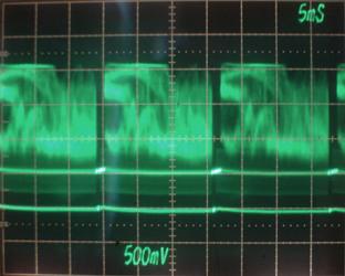
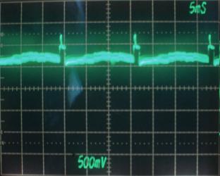
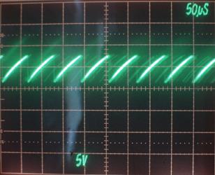
The center line of the screen is the zero-volt line. Each break in the trace shows a vertical sync, and the stuff in between is picture and horizontal sync information. The NTSC signal range according to the scope trace is -1 to 1 volts where -1 is the sync level, around -0.5 for the black, and 1 for white. To separate the sync, a circuit has to be designed to detect the negative side of the video signal and clip off the positive side that contains most of the video information. A such circuit is typically referred as a clipper or a sync separator. A simple diode or triode can be used to conduct only the negative side. However, this often requires a negative supply rail. Also the video range changes significantly after the video is fed through an amplifier. Below is a scope trace of the signal on the plate of the 12AU6 amplifier.
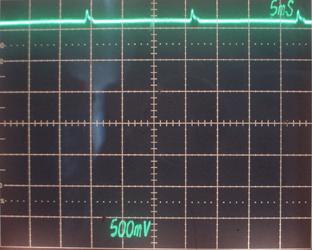
In this trace, the probe has been changed to 10x and the scope is still on DC coupling. The 12AU6 amplifier clearly inverted the video by making the sync pulse the highest voltage at around 13V and the video signal in the lower end ranging from 5 to 8 volts. The small gain is sufficient for my Tektronix's Z axis, but rather weak for the oscillators to lock onto the sync so the amplified video is fed into a high gain 12AT7 stage mainly for sync amplification. The intensity Z-axis information still can be retrieved off the plate of this tube if necessary. The following scope trace shows the signal on the plate of V2a.
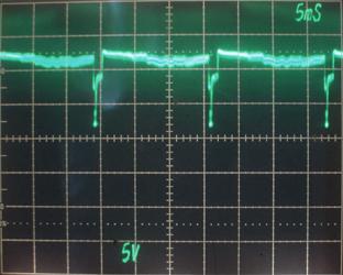
The video has been inverted once again and is at the lowest point at around 10V and the white level at around 120V. At this point the horizontal sync that is embedded with the video luminance information is strong enough for the horizontal oscillator. Sync separation of the horizontal pulses with tubes is incredibly difficult due to the horizontal sync levels being so close with the luminance. Most TV circuits have relatively stable horizontal oscillators that are not easily affected by changes in luminance. In this circuit, the horizontal oscillator is simpler and more susceptible to sync issues but a 0.01uF bypass capacitor on the grid of V4a helps prevent quick changes in luminance from affecting the horizontal. Ideally, a tuned LC circuit is used on the plate of V4a because it resonates at 15750Hz and improves stability. However, this circuit lacks a such LC circuit for the sake of simplicity. The vertical sync can be easily obtained by clipping off anything above 100V. The vertical sync separator has a large cathode resistor to provide approximately 15 to 20 volts of bias. As a result, V2b conducts some current all the time unless the grid is made negative with respect to the cathode. If V2b shuts off plate current, the plate voltage rises due to the 470K plate resistor when the grid signal drops below 15-20 volts and only the vertical sync is present from 10 to 15-20 volts. As a result, small pulses on the plate of the V2b is expected and the following scope trace indeed shows simple vertical sync pulses on the plate of V2b. The 0.01uF bypass capacitor is used to filter out high frequency noise that may result from abrupt changes in luminance.
Again the zero volt line is still in the center of the screen and a 10x probe is used, so the trace shows the signal at around 15V with pulses peaking at around 18V. The vertical multivibrator has considerable gain on the sync input so the small voltage swings in the vertical sync is sufficient for the vertical to lock onto. A 0.01uF capacitor can be placed between the Z axis and the plate of V3a to blank beam during a vertical retrace. Without this capacitor, the horizontal oscillator will create 5 to 10 visible white lines across the picture as the vertical retraces. This capacitor was left out in the schematic because I observed that the vertical oscillator often has difficulty starting up with this capacitor connected. The following scope trace shows the signal from the Y axis.
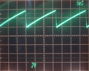
The sawtooth output clearly matches the timing of the vertical sync pulses in the previous scope trace. The period covers about 3.25 divisions multiplied by 5mS, which is approximately 16mS or 1/0.016 = 60Hz as expected for the vertical refresh rate of NTSC video. Similarly, the following scope trace shows the X output for the horizontal sweep.
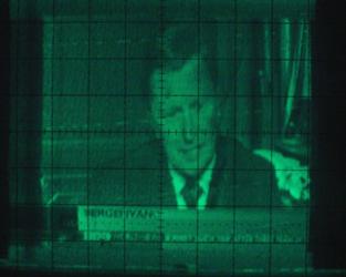
The period is approximately 1.3 divisions times 50uS, or about 65uS. The NTSC standard is approximately 63uS per horizontal line for a frequency of 15750Hz. The screenshot below gives an idea of the image quality of a TV station news anchor. A VCR was used as a tuner for off-the-air analog signals, which sadly will not work after early 2009. The stability and quality of the image is pretty comparable to most simple tube televisions of the 40s and 50s.
The last schematic is complete because it has the power and filament supply circuitry. Be aware that the circuit runs off unisolated 120V mains and can be a shock hazard if not encased properly. Note that the neutral side of mains is connected to the ground side of the circuit. This is important for both the oscilloscope and video equipment that connects to the ground side. Were the plug to be reversed, any equipment connected to this converter can be ruined so be sure to use a polarized plug. I highly recommend using a transformer that provides 120V and 6V.
To achieve a completely transformerless design, the tubes were selected so the filament series current is 0.15A. The 35W4 has a 35V filament running at 0.15A, the 12AT7 and 12AU6 are both 12V at 0.15A. The 12AU6 is functionally equivalent to the 6AU6 with the only difference being the filament specifications. The filaments of all five tubes add up to 83V so a 4.7uF nonpolarized capacitor is used to drop the remaining difference so the series string can run off 120V. The 35W4 filament is wired closer to the hot end of mains to minimize heater-cathode voltage differences.
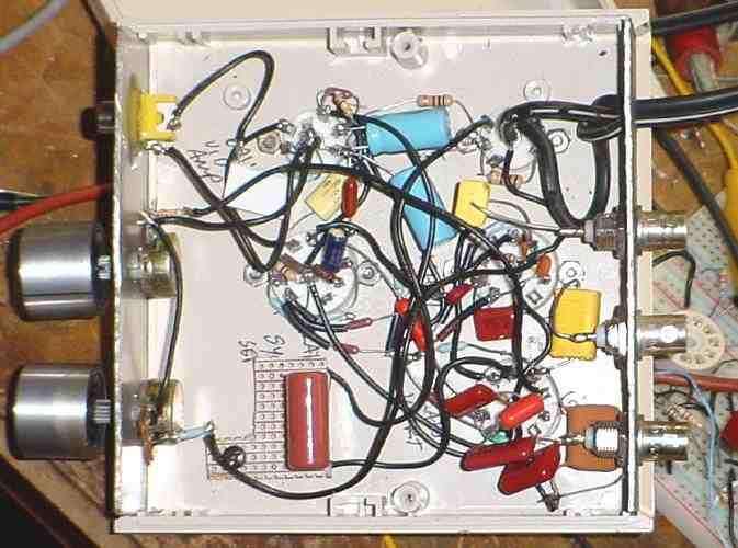
By following the last schematic, I built a final version of the tube TV-to-Scope converter in a nice small plastic case as shown in the following pictures.
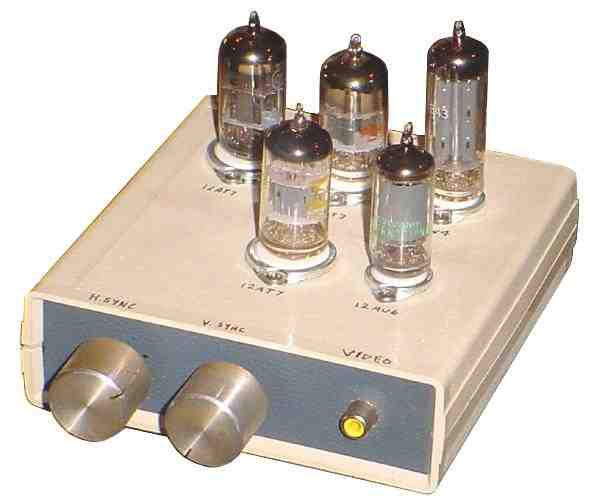
The two knobs on the front are for vertical and horizontal sync adjustment. The RCA composite NTSC video jack is also on the front panel.
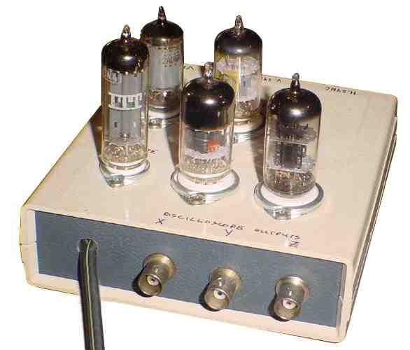
The three BNC jacks are for the X, Y, and Z axes of an oscilloscope.
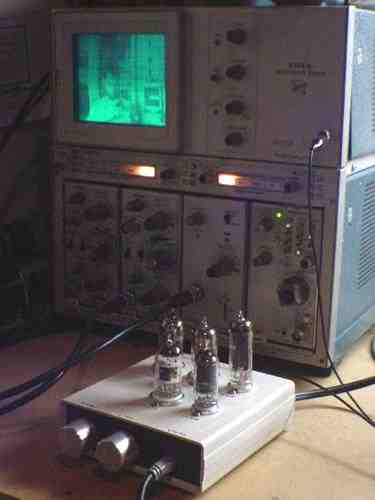
The converter and oscilloscope in operation with a video camera pointing at me.
Back to Top