Single Vacuum Fluorescent Display Clock
Return to Home
Return to Projects
A common question I often receive is how to find the pinout for VFD tubes. I never found the need to dig for datasheets because that is easily figured out by examining the innards of the VFD tube. The two components to look for are the filament and the grid. The metal mesh on the front of the segments is the grid so whatever pin has a wire leading to this component is the grid pin. The filament is a fine and often invisible wire at the front of the grid, but look for two metal posts at the bottom or top of the grid and that is most likely where the filament wires connect to. The pins connecting to those posts are the filament pins. Once the filament pins have been located, you can test it by connecting a power supply and slowly crank up the voltage from 0 to 2 volts. The filament will start to glow at around 2 volts, but if there is no visible glow at over 3 to 4 volts then you may want to reexamine where the filament pins lead to the metal posts. The rest of the pins are obviously the segments. To determine which pin corresponds to a segment, apply about 1.5 volts at the point when the filament is barely glowing and use a 12 volt supply with the negative side connected to either side of the filament. The positive end of the supply (12V) needs to be connected to the grid, and use a jumper wire from 12V to any of the other pins to illuminate a segment. Below is a basic diagram of the filament and grid pins in a VFD tube construction.
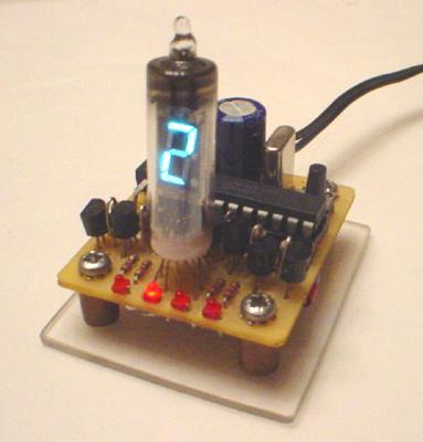
Inspired by my single numitron clock, I used a good VFD tube and made another single-digit clock. Below is a schematic of the VFD clock. The first revision of the schematic did not include the PNP transistors so the segments were controlled directly by the PIC, which works but the segments were not at their full brightness.

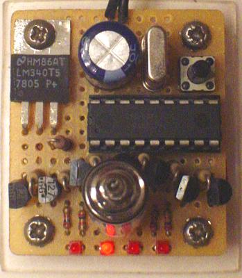
The clock is exactly the same as the single numitron clock, and the PNP transistors allow the 5V output of the PIC to control the 12V needed to fully illuminate the segments. The software can be found at my Single Numitron Clock page. I used four micro-sized red LEDs under the VFD tube to indicate which digit is being displayed (HHMM). Overall, the clock keeps time nicely. The 22pF capacitors may need adjusting to improve timekeeping accuracy.
I would like to point out that while I was building the clock, I killed at least ten 2N3906 PNP transistors due to accidents and bad testing. When the circuit is wired up as in the schematic above, I can tell from personal experience that using a jumper from ground to the base of the PNP will ruin the transistor easily. The 200K resistor is a must during testing. The idea is that the 10K resistor pulls up the base of the PNP to push the transistor into cutoff and a 5V output from the PIC will only pull down the base slightly but the transistor still remains off. When the PIC output goes low to zero volts then the base of the PNP is pulled down just enough to push the transistor in saturation so the VFD segment illuminates.
Note that the 200 ohm resistor in the schematic above is for my VFD tube, whose filament draws 20mA at 1.2V. If you construct a VFD clock then I highly recommend that an adjustable power supply is used to provide 1.2V or whatever voltage is needed for the filament to be slightly under the point when it starts to glow visibly and measure the DC current. Use Ohm's law to determine the resistor value. For example, the supply is 5V and filament is 1.2V at 20mA, so 5 - 1.2 = 3.8 volts to drop. R = V/I = 3.5V/0.02A = 190 ohms. I used 200 ohms as it was the closest value on hand. The power disspation is P = VI = 3.8*0.02 = 0.08W so a 1/4W resistor is perfectly sufficient.
Gallery of other single VFD clocks:
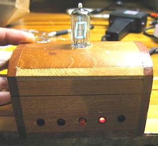
Made by Rich Bogen, this VFD clock was housed in a small treasure chest that was purchased for a buck from a thrift store.
Back to Top