My Favorite Things About The R-390A/URR
My Favorite Web sites
R-390A Home on the WWW (archived)
R-390A Frequently Asked Questions
KK4DF R-390A Restorations (archived)
Rebuilding the R-390A Receivers - an excellent guide
R-390 Mailing List
Fair Radio Sales
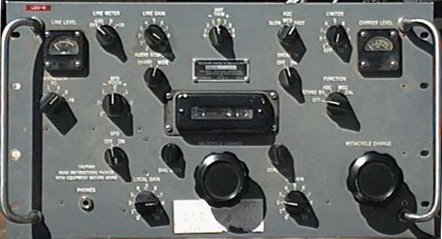
Welcome to my R-390A/URR page! The R-390A/URR, a military communications receiver built from 1955 to 1984, is still regarded as one of the best HF receivers around. Covering .5 to 32MHz in 32 bands and equipped with 26 vacuum tubes, this 75-pound boatanchor, along with its counterparts, are in a class by themselves. Unlike most typical receivers of it's day, the R-390A is digitally tuned using a unique Veeder-Root mechanical tuning display (similar to a car odometer, the megahertz and kilohertz tuning is done seperately, making for 31 bands covering of 1000 kilohertz, and one band covering 500kHz). This mechanical and electronic wonder is considered one of the best shortwave receivers around, with a noise floor at an amazing -143dB. Designed by Collins in 1955 as a low-cost replacement to its predecessor, the R-390/URR, the R-390A/URR uses 26 tubes instead of its predecessor's 32, and mechanical filters in place of crystal ones. My R-390A was built not by Collins, but Electronic Assistance Corporation (EAC), a division of Hammarlund, under a 1967 contract with the U.S. government. EAC made over 10,000 R-390As under their 1967 contract, and produced over 15,000 of them in total, more than just about any other R-390A manufacturer (even Collins, who produced surprisingly few of them). My R-390A is fairly complete, is in prety good shape, and works quite well. The red Dymo label on the top left corner of the front panel reads "LES-6," and the paper label below the Kilocycle Change knob has several things scribbled on it like "58205387555" (a slightly-abbreviated form of the R-390A's NSN, or National Stock Number), the manufacturer, the serial number, the date 3/20/74, and things I cannot identify like "819AK," "LIR-59," "Mullen," "Line #151," and a stamp reading "NOTPME." If anyone can identify what these markings (especially the NOTPME stamp) mean, please email me using the email address at the bottom of the page.
UPDATE: Thanks to a kind e-mailer, I now know what NOTPME means! It refers to a military calibration lab, and means that either no calibration is required, or that it hasn't been calibrated. From what I know about the radio, either could fit. Thanks much to AT1 Brent Williams for this explanation.
Site Navigation:
Return to the boatanchors page!
Return to the old radio page!
My R-390A Timeline
March 7, 2003: Acquired my R-390A, along with an R-392/URR (vehicular version of R-390/URR), and an R-48/TRC-8, from a former instructor. All three are said to be in nonworking condition, but otherwise appear to be in good shape.
March 20, 2003: Took several pictures of this set (links to them can be found on my boatanchor page). Discovered that two 5814A tubes, along with their W.P.M. tube shields, are missing. Hopefully, I will rectify this situation soon enough.
April 26, 2003: Bought a pair of 5814As at the NEARC swap meet for $5.
May 10, 2003: Took a closer look at the 3TF7 ballast tube in my R-390A, and discovered that it was open. Tested it with a continuity tester, and got the same results. Looks like I'm going to need to replace the most-expensive tube in the entire set.
May 16, 2003: Bought a 3TF7 in an eBay auction for $30. Am also planning to make a substitute tube which will act as a sort of ballast most of the time, saving the life of the real 3TF7.
May 24, 2003: Ordered replacements for both C553 (DC blocking capacitor for the mechanical filters; fries them if it goes bad) and C549 (causes bad audio if it goes bad), as well as radial electrolytic capacitors to replace the innards of can capacitors C603 (3x30�F) and C606 (2x45�F). Hopefully replacing these parts, as well has making a metered variac setup to power it up with, will allow me to power this set up without risk of fireworks.
June 3, 2003: Received the ordered parts from Mouser Electronics, which means I am almost ready to begin the restoration projects (re-stuffing the filter caps will be first, followed by the IF deck work). Also acquired some new parts for my planned metered variac device (schematic available here). Originally, I was going to use a somewhat beat-up 10A General Radio Variac, along with a 5A or larger isolation transformer, but I recently acquired a 3A Powerstat unit which should suit the application a bit better (will also allow me to use a smaller isolation transformer, not to mention fuses).
June 8th, 2003: Began work on re-stuffing the can capacitors. I cut open the triple-section 30�F can capacitor and removed its original innards (which were still moist) without incident, but ran into problems when I tried to solder in new components. Turns out that the pins are entirely aluminum, which refuses to be soldered to under most circumstances. I will have to undertake different measures, which will include drilling out the original component leads from the semi-hollow pins, and either crimping in solderable leads or tapping them for solderable screws (see this page for more on the process). Also, I am awaiting the arrival of some twin-ax connectors, which should help in making a suitable antenna connector for this set.
June 10th, 2003: Cut open the double-section 45�F can capacitor, and removed the innards (the process went a bit smoother this time, thanks to what I learned from the first one). I then used a drill press to remove the remains of the original capacitor section contacts in both cans, which should greatly simplify the process of inserting the new capacitor leads into the hollow section of the octal contacts. Also, I got those Twinax connectors today; one of them will be terminated in a PL-259 or other RF connector, and another will be saved for when I have a true balanced antenna setup.
June 11th, 2003: Soldered extender leads onto the 33�F capacitor which will be above the other two in the arrangement. Taped two of the 33�F capacitors together, then taped the third one above the other two. Soldered the negative leads together, trimmed all the leads to fit, then crimped the leads into the octal pin contacts. All that's left to do is to epoxy this thing back together, then get to work on the dual-section cap (which should be easy compared to this one), and finally unearth the IF deck from the set so that I can replace the two trouble capacitors (C553 and C549).
June 12th, 2003: Taped the two 47�F capacitors together, soldered their negative leads together, then positioned the leads into the contact pins and crimped them in. Also bought some J-B Weld two-part epoxy, which should be able to glue the cap cans to their bases.
June 14th, 2003: Mounted the capacitor cans in C-clamps, applied masking tape 1/8" above where the seam would be, and applied J-B Weld to the seam area. After around an hour, I removed the masking tape, leaving a clean-looking seam area. In a day or two, these caps should be ready to be put back in the receiver, and the process of replacing the problem caps in the IF deck can begin.
June 16th, 2003: Took both cans out of the clamps. At first glance, both cans looked to be solid. I then tried to fit the triple-section 33�F can capacitor to the radio, and found that the mounting clamp was a bit off. I then loosened the clamp, attempted to align it, and felt the entire can turn instead of just the clamp. Sure enough, torquing the can had caused the epoxy joint to give way. I then proceeded to remove the remnants of the epoxy (which was surprisingly easy to take off), mixed a new batch of J-B Weld (this time making sure that the "steel" and the hardener were in equal proportions), and glued the bottom edge of the can to the base instead of the side. I attempted to simulate the same sort of force acting on the double-section 47�F can capacitor, but it didn't give way, so I decided to leave it alone.
June 18th, 2003: After two days of letting the epoxy dry, I took the triple-section 33�F can capacitor out of the clamp. This time around, the mounting clamp was much easier to readjust, and I trust the new glue joint more than the old one (I'm still a bit skittish about the double-section 47�F can capacitor, but since it doesn't show any signs of coming apart, I'll leave it as-is). I then readjusted the clamp for the double-section 47�F can capacitor, made labels for each cap (stating when it was re-stuffed, and what with), and reinstalled them in the set. Now that this part of the process is finally over, I can concentrate on the other part.
July 3rd, 2003: I have now begun the process of replacing the problem capacitors in the IF deck. Per the instructions on Chuck Rippel's C-553/C-549 page (though he should reverse the second and third steps, since two of the three small connectors are nearly-impossible to remove with the large multi-pin connector still in place), I carefully removed the IF deck chassis from my R-390A, and proceeded to inspect the innards. Interestingly, most of the capacitors in there are yellow Aerovox mylars, while there are still some "bumblebee" molded-paper types in there as well. I have located the capacitors I need to replace, which I will replace soon.
July 7th, 2003: Clipped C-553 from its leads, removed the pieces of Teflon tubing covering each lead, and unsoldered both leads from their connection points. Covered the leads of the replacement Orange Drop capacitor with the tubing, cut the leads to fit, and soldered them in place. Unsoldered C-549 from its turret block, cut the leads of the replacement Orange Drop capacitor to fit, then soldered it in place. Put the R-390A back on the bench, screwed the IF deck back in, reconnected all the connectors, and tightened the knob clamps back onto the shafts coming from the IF deck. This concludes the preventative-maintenance portion of the restoration process, and means that I can now get to work putting together a device which will allow me to bring voltage to the receiver slowly.
July 10th, 2003: Built a device which would allow me to read AC amps with my Simpson 260 VOM, and also built a device which would allow me to derive audio from the set via the Diode Load point. Connected the set and the VOM to the AC amps device, connected the AC amps device to the Variac, connected the Diode Load device to a small stereo receiver, and hooked a long piece of wire to the balanced antenna input using one of the twin-pin plugs. With the R-390A's function switch set to OFF, I began slowly turning the Variac's knob to see if the contacts in the power-control microswitch were shorted out or not, and saw no signs of life from the set (as expected). Turned the Variac down, set the function switch to STAND BY, began slowly turning up the Variac, but stopped when a slight buzzing was heard. Turned the Variac back down, set the function switch to AGC, and slowly began turning up the Variac again. Slowly but surely, I began to see signs of life from the receiver, as the tubes and dial lights began to glow. With the Variac at 120, I couldn't hear any noise from the speakers, so I began fiddling with the knobs. Soon, I was hearing static, and before long, I'd managed to tune in WBCQ (though it was located somewhere near 7,424KC instead of 7,415KC; looks like some sort of alignment may be in order). Began tuning around on some of the bands, managing to tune in some foreign-language stations (one of which had a musical station identification, which came through with booming fidelity; those who have raved about the quality of audio available from the Diode Load point were right on target). Eventually, I decided to test dial alignment on the BC band, and was able to adjust the set so that WRKO came in at 680KC. For the most part, I considered this test a success; apart from the apparent misalignment on at least one band, the set works great. I took some video footage of this first test, and still photos captured from that video can be found here.
July 11th, 2003: Did some more listening with the R-390A. Armed with freshly-printed out pages from the manual (a rather large scan of which can be found here) detailing how to prepare the set for reception, as well as calibrating the dial, I was able to use the set more effectively. Discovered that the alignment was not nearly as off as previously thought, as WBCQ came in around the area where it should be. After listening to Allan Weiner Worldwide, as I always do on Friday nights (reception wasn't too good, thanks to some sunspot activity, but I was able to faintly pick it up when my Grundig Mini-World 100PE couldn't), I decided to do some bandscanning. First, I decided to check the 80M ham band, where I was able to easily decode SSB transmissions (realigned the BFO Pitch knob to better indicate where the zero-beat point was), as well as AM. I then switched to the 49M band, where I was easily able to pick up BBC World Service (which I haven't heard much on my other radios since they stopped direct transmission to North America) smack dab at 5,975KC, as well as many other broadcasting stations. Afterwards, I decided to do some DXing on the AM broadcast band. I was able to easily distinguish stations within 10KC of each other (just as a good AM radio should). This set has been performing beautifully so far.
July 12th, 2003: Equipped the set with a longer antenna wire; now reception is much better. Also was able to zero the carrier level meter, which means that I can now more-accurately tell how strongly the station I'm listening to is coming in (numbers I'm getting are typically in the 40dB range, sometimes going to 60 or 80dB). Attempted to listen to Radio Timtron Worldwide at 6PM EST on WBCQ, but their normal frequency (7,415KC) was coming in only weakly, so I decided to try out their new 5,100KC frequency that I'd heard about the previous night. Sure enough, it's doing a simulcast of the programming on their normal frequency, and it was coming in very strongly. Over the course of the evening, reception on that frequency faded a bit, and reception of their normal frequency improved greatly. Thanks to the newly-zeroed carrier level meter, I was able to get a fairly-good reading of their signal strength (hovered around 20-30dB at 9PM EST), and have made out a reception report for this new frequency, which I will send in to them in hopes of getting a WBCQ QSL card.
July 19th, 2003: Decided to substitute my jumpered 12BY7A for the 3TF7 I had been using to this point. At first, the loosely held-on jumper wires made for an intermittent connection, causing the tube to fade in and out (taking the reception with it as it faded out, and getting reception back when it faded in), so I decided to solder them on. Now, the set works just as well as it did with the 3TF7 in that spot. Hopefully, this will save me from having to buy a 3TF7 too often.
July 21th, 2003: Began work on the devices that would allow me to use my R-390A at the upcoming NEARC swap meet, where I was planning to enter it in the metal radio category in the contest. The device I decided to build first was a miniaturized version of the variac/amps-to-volts converter combination used to power up the 390A each time I use it. For an enclosure, I selected the case of an old solid-state regulated 12V power supply which had a fried transformer. After ripping out all the guts, I prepared the components slated to be used, and then drilled holes for the shaft and alignment pin of a Powerstat 10B variac.
July 22nd, 2003: Continued work on the variac-based tester device. Drilled and punched a large hole for the three-prong outlet for the device, but realized that the hole was too far to the right and too far down, as well as being a bit too small (the hardened steel used to make the case made it nearly-impossible to file, but I managed to get it large enough). To compensate for the misalignment, I rearranged the contacts of the variac, and removed the original power switch. After installing a new power switch, which I had to put around back due to the lack of room in the front, I then proceeded to wire the device up. Checking the output of the device with a multimeter showed that it appeared to be working as it should.
July 23rd, 2003: Tested the variac-based tester device using the R-390A as a load. Surprisingly, it turned out to be able to take the load of the set well. Later on, a friend suggested to me that I should build a speaker which would be fed by the local audio output on the back of the 390A, instead of simply feeding a small amplifier/speaker combination from the diode load point, as originally planned.
July 24th, 2003: Began work on the local audio-fed speaker. For the cabinet, I selected a large faux-woodgrain speaker originally used on a crappy 1970's all-in-one stereo system. After discovering that it used a 4 inch speaker, I promptly removed it and selected an 8 inch Realistic "Americana" coaxial car-type speaker to take it's place. I then proceeded to use a hole saw to drill eighteen one-inch holes in the baffle to match the seven that were already there for the tiny original speaker. Later on, I went to Home Depot and purchased a 18x24" piece of 1/4" thick Plexiglas for around $11, along with a set of metal brackets, which I would use to construct a see-through chassis cover for my R-390A.
July 25th, 2003: Began work on preparing the plexiglas chassis cover. Cut score lines which would allow the cover to match up with the sides of the main chassis, then attempted to break the pieces off. Unfortunately, the plexiglass decided to break where it wanted to instead of along the score lines, causing a jagged edge that made for a cover too small. To cover up the damage, a table saw was used to make some shallow cuts in the plexiglas to even up the sides of the cover. What I was left with was a cover which was more than 1" narrower than originally desired, but I decided to make do with what I had. A drill press was then used to slowly drill, then countersink, twelve 3/8" holes for ventilation purposes. Then, I mounted the speaker to the newly-drilled baffle board, and mounted the impedance-matching transformer (a 70V public address system matching transformer wired to convert 500 ohms to 8 ohms) inside the speaker cabinet. I then glued the baffle board to the front of the cabinet, attached some suitable grille cloth/foam over the front of the speaker, and tested my whole setup. Surprisingly, the local audio-fed speaker sounds almost as good as the diode load audio, especially with the good-sized coaxial driver (versus the 5" driver used for the portable amp/speaker combination being fed with diode load audio). After that, I packed up all the stuff, and prepared for tomorrow's swap meet.
July 26th, 2003: Brought my R-390A to the swap meet for the contest. After hauling the 390A to the table for the metal radio category, I began setting it up for demonstration purposes. Not too long after I began setting it up, someone came along and entered in a Racal RA-17L British boatanchor into the contest; it looked similar in ways to a Collins 51J-4 (also known as the R-388/URR), and was installed in a cabinet. After completing setup on the 390A (due to space constraints, I only used the local audio-fed speaker), which took nearly an hour (especially since I accidentally lost two of the Utah Plate's mounting screws in the geartrain; fortunately, I was eventually able to retrieve them), I attempted to tune something in, but was getting nothing but buzzing on the lower bands, so I left it with the dial set at 7,415KC in anticipation of the arrival of Allan H. Weiner, the head of WBCQ. When I showed him the set, he was quite impressed, but told me that WBCQ wouldn't be on the air until the afternoon, so I decided to tune around in the higher bands. At around 14,610KC, I encountered a series of slow morse code signals, which I soon traced to the telegraph sender simulator which was sitting at a nearby table (complete with electromechanical sounder). I left it tuned to that for awhile, but later retuned it to a BC band station which was playing oldies. Over the course of four hours, I occasionally saw people twiddling with the knobs, but left them alone. At around noon, I was there to watch the contest chairman putting out the ribbons for the contest. Amazingly, I managed to get second place, while the Racal sitting right next to it didn't place! First place went to a Philmore one-tube radio from the '20s or '30s, and third place went to a small Silvertone table radio from the '50s. I didn't mind getting second place behind the Philmore, since this wasn't a boatanchor-oriented meet to begin with. I did get many nice comments about my set, as well as my TransOceanic article, which had been printed in the latest club newsletter. All in all, I considered it a successful outing.
August 4th, 2003: Prior to this day, everything has been going relatively well with the set. Unfortunately, during a recording session of a recently discovered local oldies station on the BC band (no commercials, so it makes for some killer mix tapes), I've begun hearing a loud buzzing noise which almost completely swamps out much of the broadcast band. All but the strongest BC stations in the area (WRKO, WEEI, WBZ, etc.) seem to be affected by it. I'm not quite sure what's causing it at this point.
August 5th, 2003: I decided to do some testing to see if the exact location of the buzzing can be located. Using an old Panasonic transistor radio, I was able to get relatively-clear reception of the oldies station until I got within a few feet of the radio, upon which the same buzzing can be heard on the transistor radio. It appears to be loudest if held up to the line cord of the R-390A itself, and is audible on the transistor radio whether or not the set is turned on, whether the variac controlling the 390A is turned up or down, and whether or not the power switch supplying power to the variac is on. The only way to get rid of the noise is to unplug the 390A altogether. This makes me suspect the line filter to which the set's line cord connects to, but I'm not quite sure how I can prove this as being the source. Later on that night, I decided to do yet another interference sweep using the transistor radio, and starting inside the house. With much buzzing coming from the 390A's speaker, I took the transistor radio inside the house, and was able to hear some very loud buzzing in there as well. I managed to trace the buzzing to a dimmer-type light switch in the kitchen, which wasn't turned all the way up. Fixing this eliminated the buzzing being received on the transistor radio, and when I returned to my shop to check on the 390A, the buzzing has been all but eliminated at this point (except for a few intermittent bursts of it occurring every once in a while). I doubt that this problem has been solved, but I will keep an eye on it.
August 6th, 2003: This morning the buzzing has returned, so I decided to take some quasi-scientific tests on how much noise I'm getting using the line-level meter which the set is equipped with. With the line meter control set to 0, and the line gain control set to 4, the base noise level seems to hover around the 25 mark on the meter's lower scale. Music levels seem to be in the range of the 50-75 marks, with peaks occurring near the 100 mark. After a while of this testing, I decided to take some measurements of how the noise affected other bands. All throughout the 1000-5000KC bands, I am getting several frequency ranges (each around 600KC in width; one example is the 1100-1700KC range) which exhibit relatively-large amounts of noise, with silence in between each band. By the 7000KC band, much of the noise seems to have disappeared. Later on in the day, the interference received seemed to be limited to spatters of static which occurred every few seconds.
August 7th, 2003: The noise seems to have quieted down for the time being, though I have been once again getting intermittent bursts of band-swamping buzzing every once in a while. I am going to keep monitoring this problem to see what it does next.
August 8th, 2003: I think I may have finally figured out what is causing this mind-boggling problem! After receiving the buzzing yet again this morning, I decided to see what effect disconnecting each conductor of the line cord from the set would have on the interference (with no power being applied except what was transmitting the buzzing, of course.) While removing the neutral lead from the line filter, I noticed that my attempts to remove the retaining nuts were causing the wires to move quite well along with the rest of the mounting hardware. After managing to disconnect this lead, I moved on to the hot and ground leads, which didn't turn nearly as well. The noise only went away when all three conductors were removed, which disappointed me, so I began reattaching the power leads again. While trying to retighten the neutral lead, it began turning quite well in the opposite direction, which caused its previously-bent connecting lug to shear off from the wire. It was at this point when I noticed a crack extending along the entire circumference of the ceramic insulator insulating the mounting screw from the case of the R-390A. This crack, which was hard to notice due to the silver coloring on the ceramic, allowed the mounting screw to turn 360 degrees, while still holding it on; I believe that this caused a loose connection which acted like a tiny crystal radio, taking any received interference and radiating it along the leads of the line cord. This was easily picked up by the antenna on the sensitive R-390A, but a transistor radio needed to be close by the cord to be affected much by it. All I need now is a replacement line filter, preferably one with the ceramic insulators around the input terminals (my set only has two small holes for the input terminals to stick out of, not a large hole like on some other 390As; once I get this, I'll be back in business, but until then, I'm out of commission. If anyone has an R-390A line filter that they can spare, please email me using the email address at the bottom of the page.
September 5th, 2003: Thanks to a kind member of the R-390 Mailing List, a line filter from another '67 EAC R-390A should be arriving soon. After that, I can take out the makeshift connections I was using to get around the line filter, and return this set to normal. In the meantime, to save the connections as well as the power switch, I have been using an old Wuerth "TV Life-Saver device which I purchased NIB at a swap meet. It is a surgistor-based device which is meant to limit the flow of inrush current; it seems to work, but I'm anticipating early failure because it puts out a puff of smoke each time I turn the 390A on (have heard that those things tend to fail after a period of time, but that may be quickened since the set probably draws more current than the device can handle upon turn-on).
September 10th, 2003: Received the line filter today. Its terminals, which also appear ceramic-based, are in much better shape than the old one. It was relatively easy to install once I was able to get my stubby screwdriver in that cramped space, but I soon found that attaching the leads from the new power cord were going to be a major pain in the rear end. Reattaching them isn't much of a problem, but routing the wires so that it all fits within the terminal cover is quite a challenge. After going through many sets of crimp lugs trying to get it attached properly by resizing the wire lengths, I decided to save it for another day.
September 11th, 2003: Decided to take another crack at the routing. Using what I had ended up with yesterday, I decided to try going from the up part of the terminal cover instead of the lower part (where I thought there was more room, but actually wasn't). I was able to get a satisfactory routing, so I tightened the nuts on the terminals, replaced the terminal cover, then got to work attaching the old metal military three-prong plug to the length of cord. After removing the old cord from the plug, as well as recording the length of the original lead-in wires, I got to work tinning the ends of the new wires to match the old ones (which wasn't trivial, since the new wires are much thicker than the old ones). After that was out of the way, I bent the tinned ends to a satisfactory curve, made note of the orientation, and tightened the terminal screws down on the hot and neutral wires, which wasn't too easy due to the stiffness of the tinned 14 ga. wire. I then reattached the ground prong (which is separate from the plug itself, since it is a three-piece affair), attached the ground wire (which actually comes out the back of the plug) to an external green screw on the prong assembly, then made sure that it made continuity with the case. I didn't have time to try it out tonight, but it should work if nothing is seriously wrong with either the new line filter or my wiring.
September 12th, 2003: Tried the R-390A with the new line filter today; it's much quieter than it was with the broken line filter, and even quieter than when I had the power cord going directly in (which was quiet on the BCB, but still had buzzing effects on parts of the 2MC band). I'm very glad that I got the set back in good working order, because this night proved to be the best I'd ever encountered for BCB DXing; I was getting News 940 from Montreal, Canada, like it was a local station! I even managed to get WSM 650 (which I had wanted to receive for years), as well as WTAM 1100 from Cleveland, and WCBS 880 from New York. Typically, I'm never able to get stations much past the New England area, but for at least a short period of time, I was getting the kind of BCB reception that I'd only dreamed of.
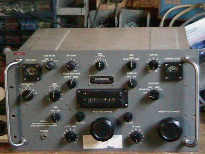
October 15th, 2003: Thanks to another kind R-390 Mailing List member, I now have a top cover for my R-390A! According to the sender, it was originally on a Motorola unit, and apart from a bit of dirt and tape here and there, it's in excellent condition. Finally, my set is just about complete.
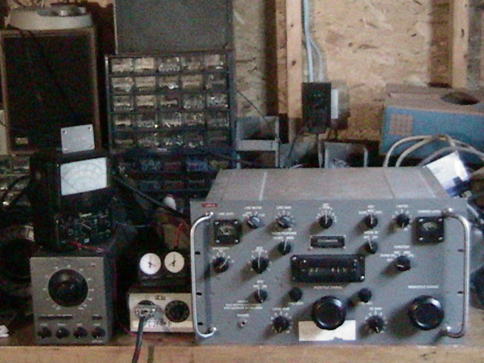
October 17th, 2003: Took some pictures of the R-390A in it's current state: they can be found here, here, and here. The first one is a straight front view of the set, the second one is of the set with it's new top cover, and the third one is of my current listening setup, nicknamed "AN/CRM-114" (in homage to the fictional discriminatory radio receiver in the movie "Dr. Strangelove"). To the right of the R-390A can be seen my small variac device, a dual-time travel alarm clock, my Advent 420S receiver (for use with the diode load point), my Simpson 260 VOM (for current monitoring), and two of my speakers (one of which connects to the 420S, while the other connects directly to the 390A), not to mention the junk perpetually strewn about my workbench (I'm planning to move the R-390A out of my workshop Real Soon Now).
July 5th, 2004: During a test, the 12BY7A ballast replacement's filament failed after nearly a year in operation, causing the set to go dead. I have put the 3TF7 back in for the time being, but will replace it soon with a suitable substitute.
July 17, 2004: Entered the R-390A in yet another swap-meet contest, this time in one dedicated to boatanchors. Unfortunately, I once again came in second, this time to a Hammarlund-designed SP-600JX which had chrome accents around its dials, and was mounted in a case.
March 31, 2007: Yet again, the ballast tube has blown out. I have just purchased a replacement 3TF7, but I really need to find a more permanent solution to the issue, as this exercise is getting a tad expensive, and 3TF7s aren't getting any cheaper.