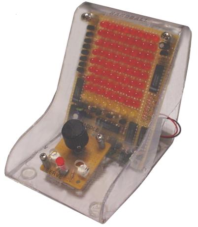
Handball
Return to Home
Return to Projects
During the designing stage, I learned of a mistake in the concept of reversing the ball's direction when it reached the end row/column because the signal goes through the logic FAST and would barely give the end LED sufficent time to glow before the ball reverses direction. So the LED matrix was cut down to 8x8 LEDs, and the first and last output of the LM3914 could be used as the reversing signal. Unfortunately, when the circuits were built the first output stays on the whole time, and I was unable to figure out why so it was either cutting the matrix down to 7 by 7 LEDs or putting an approximately 1/3 to 1/2 second time delay on the second output of the LM3914s to allow the end LEDs to glow. I chose the latter method and got a successful test on the horizontal movement using a 555 timer for the delay. The vertical circuit was built, but first the paddle controller and the associated logics has to be built for collision detection at the bottom.
The paddle controller was simply another LM3914 with only four outputs wired for the four paddle positions, and a simple pot between 5V Vcc and ground as a voltage divider with the swiper connected to the input of the chip. The associated logics for collision detection between the ball and the paddle is a bit tricky. First of all, there are only four paddle positions, thus four columns on the ball's matrix. However, the ball has 8 possible column positions so four OR gates are inserted on every two ball columns and whenever the ball is in either column in the paddle's current two-LED long column, the output is HIGH (1). The OR gates are simply two diodes and one pull-down resistor, so the output is naturally LOW (0) without any input signals. Next, there are AND gates that combine the OR gate signals with the position of the paddles. For instance, if the paddle is in column 1 and the ball is in column 1, the AND gate outputs HIGH (1). If the column of either the ball or paddle do not match, the AND gates output LOW (0). The outputs of the four AND gates are all combined by three OR gates to create a single signal that goes HIGH whenever the ball enters the paddle's column. The last thing to do is to use another AND gate using the column match detection signal and the bottom row signal of the LM3914 to reverse the vertical motion of the ball. That way the ball has to be at the bottom row and in the right column to bounce off the paddle. However, because the bottom row signal from the LM3914 is always on for some reason, the 2nd row output is sent to another time delay circuit. Several pull-down resistors and inverters were necessary to ensure the inputs of the logic were done correctly.
If you can get output 1 on the LM3914 to work then no time delay circuits are necessary and the reverse signal would be obtained from output 1 rather than the delayed output 2.
Below is a basic block diagram of how the collision detection logics are done.
The inputs of the LM3914s are analog so I used a 4013 dual flip-flop, two capacitors (one for vertical and one for horizontal) to generate the analog voltage signals. The capacitor is connected to 5V (Vcc) via a 1K and a 5K pot for variable X/Y speeds so the capacitor always charges up when you turn the game on. The reversing signals from the LM3194 and time delays are fed into the Set and Reset inputs of the 4013. The output is hooked up to a NPN transistor that is in parallel with the capacitor through the 5K pot to either allow the capacitor to charge or discharge. When the output of the 4013 goes HIGH as a result of the 10th output of the LM3914 for either X or Y position going HIGH, the transistor is turned on and discharges the capacitor, thereby making the ball in the opposite direction.
One extra thought: If the LM3194 worked properly, the matrix probably should be 10x9 because the first output of the vertical LM3914 should be left floating so if the ball misses, moving the paddles around won't inadvertently trigger the reverse circuits. I believe the reason my circuit worked without taking this in account was because ouput 1 of the LM3914 was always on, so I used the second output with a time delay. If the ball missed the paddle, the outputs of the LM3194 are all off except for output 1 which has no effect on reversing and that is where the ball settles until the SERVE button is pressed.
PROBLEMS:
Most of the problems were related to the LM3914 not turning off output 1 when other outputs are on. This may be due to incorrect resistor configrations that was unknown to me at the time. To avoid another chip for the fifth AND gate in the ball-paddle collision detection, a homemade AND gate using transistors was constructed. The gate had some minor problems because it seems one transistor has a problem stabilizing when the other transistor turned on when ball enters paddle's column, but a 1uF bypass capacitor on that transistor helped.
Below is the schematic diagram of how this game was built.
NOTES ON PARTS USED:
The bad move was using the LM3914 in the first place. Any other up/down counters might work such as digital-driven vertical and horizontal instead of analog. This game is a nice simple example of combining both analog and digital technologies.
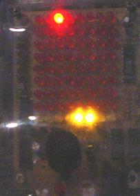
Below is a GIF simulation of the game in operation (my circa 2005 fast-download alternative of using the large MPEG movies or Youtube).