PongMan
Return to Home
Return to Projects
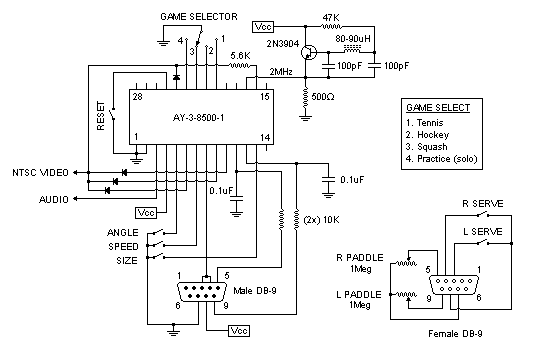
The PONG game system consisted of GI's (General Instruments) first and well-known "PONG-in-a-chip," the AY-3-8500-1. More information can be found on the AY-3-8500-1 at http://www.pong-story.com/gi.htm. Note that the AY-3-8500 is the European version that outputs PAL, the AY-3-8500-1 is the U.S. version that outputs NTSC. The chip is capable of playing four PONG variants and the circuit is pretty simple. Moreover, I was able to locate some room in the TV for the chip, however it was a little bit less than a quarter of an inch in height. I had to bend the pins of the chip to make it more flat, I also used 1/8W resistors and flat ceramic disc capacitors for the components. The 2MHz oscillator was too large for the space I had selected for the chip, so I had to put the oscillator in another sufficent space in the TV. The 2MHz signal from the oscillator was carried to the chip through a small shielded cable. Below is the schematic of the PONG game system using the AY-3-8500-1.
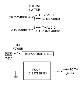
The serial port in the schematic is for use with the Atari paddle controllers I had, but one could build the controllers if desired. I used mini switches for the game so it would fit in the TV, but I still had to cut some of the TV's printed board and rewire the trace lines that were cut out with the board. The weird A/V jack was removed and made room for two slide switches for POWER and TV/GAME. The TV/GAME switch flips back and forth from TV mode to Game mode by connecting/disconnecting the TV's audio/video and the game's audio/video. When the project was completed, there were several minor problems, especially related to the TV. When I received the TV, I was told it had blown the fuse viciously, though the TV still worked just fine after the previous owner shorted the fuse. However, after 5-10 seconds of operation on batteries, the game started working incorrectly, aka. "erratic operation" because the battery's voltage was too low. Both the TV and game operates on the same pack of four C batteries. However, I measured the voltage of the batteries and it dropped down to around 4.6-4.9 volts when the TV was powered up. I disconnected the chip from the batteries and gave it 6V, then reduced the voltage slowly and the chip began to fail at 4.6V, which explains why the game was not operating correctly. My solution to this was to add two AAA batteries, which could fit in the battery compartment after a few modifications. The game was rewired to operate off BOTH the four C batteries and the two AAA batteries, for a total of about 7.5V when the TV loads the C batteries down to 4.5V. Afterwards, the game was working properly and no further problems were encountered. Anyway, below is the schematic and layout of the A/V input and power supply modifications for the game.
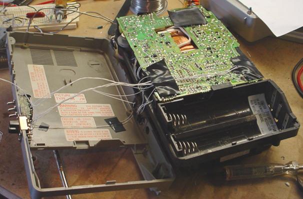
Rear of TV during assembly
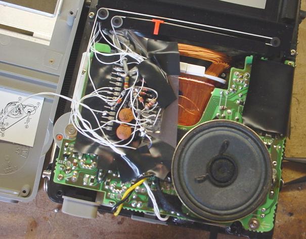
Front of TV during assembly; the AY-3-8500-1 is visible next to the speaker.
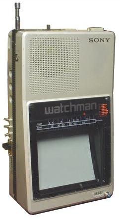
The completed Sony Watchman with the game enclosed
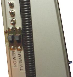
Switches for game power and TV/game selectioin.
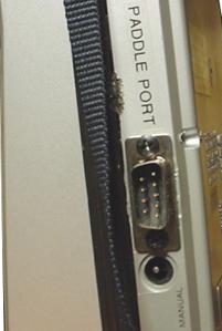
Serial port for Atari paddle controllers.
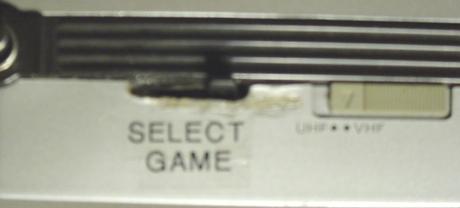
Game selector switch on top by the TV band selector.
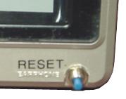
Front bottom view of the TV where the earphone jack was replaced with a reset button for the game.
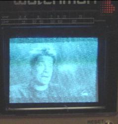
Sony Watchman in "TV mode"
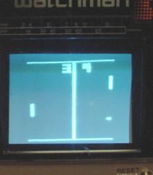
Sony Watchman in "Game mode"
Back to Top