TV Tube Regenerative Receiver
Return to Home
Return to Projects
In a dusty corner of my closet was a crystal radio someone built from around the fifties. The crystal radio came with a bunch of other stuff in a box I had bought from an auction. It needed high impediance earphones and I don't carry anything of this sort but a high gain amplifier is a nice subsitute. After dusting off the crystal radio that sat in its niche for several years, I hooked up the earphone terminals to the input of the 6JT8 amplifier and connected a measly 6 foot antenna to the radio. To my amazement, the crystal radio actually picked up at least three stations. I thought to myself, if that simple radio consisting of a mere coil, a variable capacitor, and a single 1N34 diode can pick up stations then I should be able to build a radio that is far simpler than the superheterodyne I built years ago. Before the superhet, I had built various crystal and regenerative receivers that never seemed to work, but in hindsight I realize that these radios may have almost worked but I lacked the experience and knowledge back then to get them running. It's quite a shame that none of these radios I built in the past exist anymore because I stripped the parts to use in other projects.
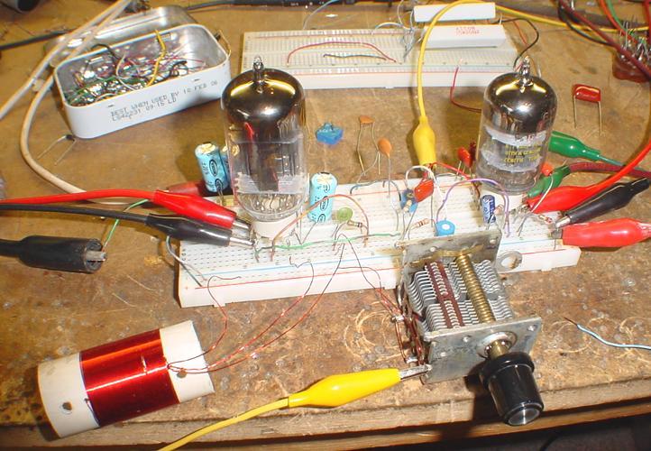
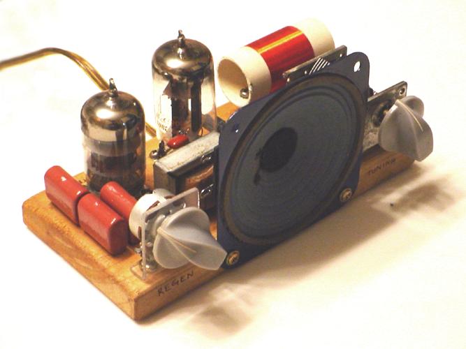
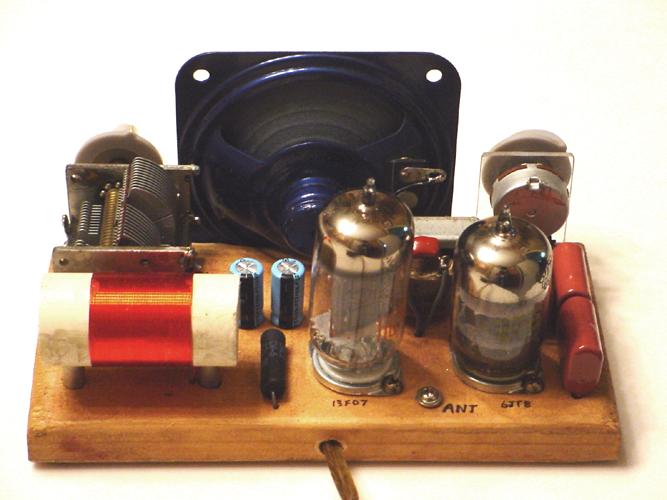
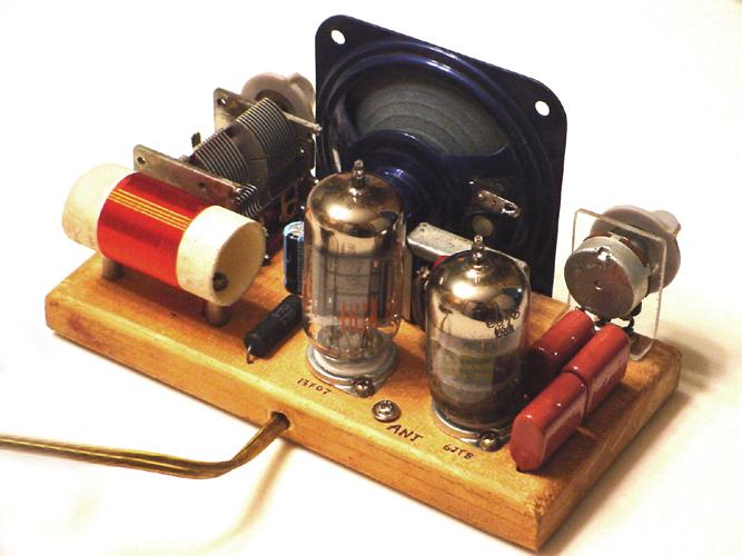
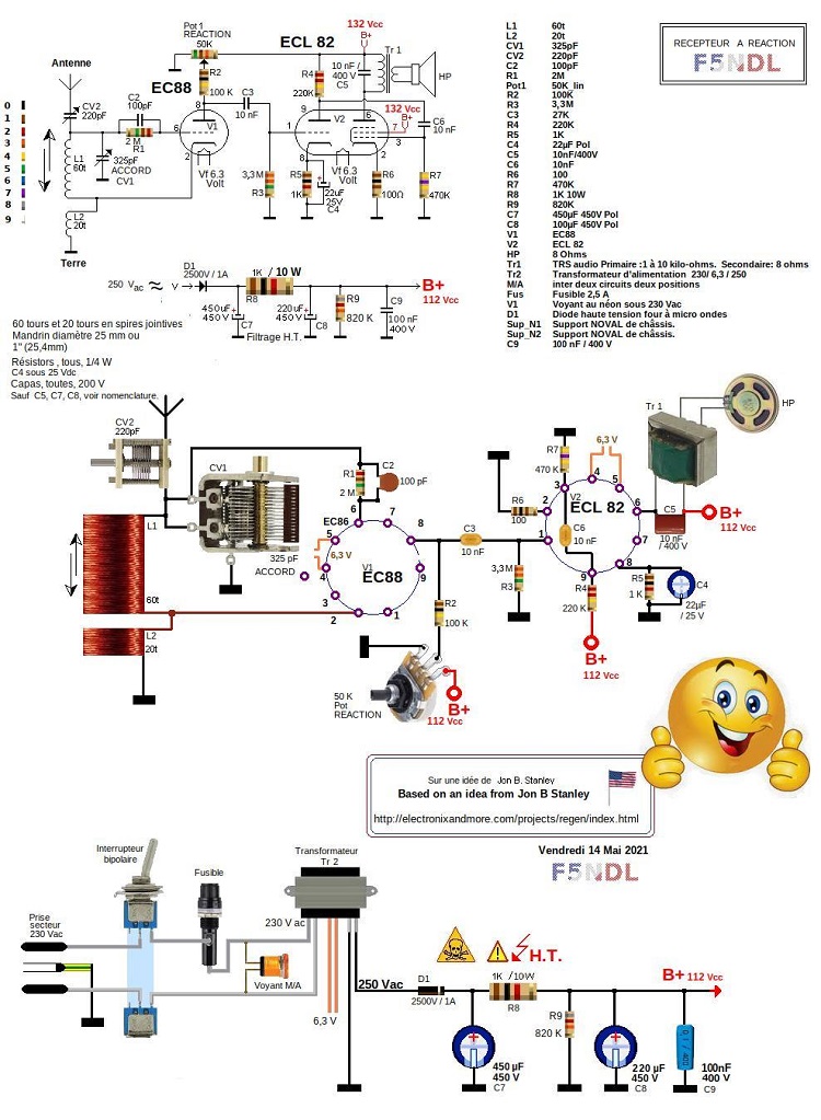
So, some eight years later I took a stab at building another regen receiver. After searching around online, I found a 12AT7 based regen that seemed simple enough to build. To my amazement, the radio worked on the first try so the next step was to find another TV tube that contains a rectifier and high gain triode in one package. During experiments when the 6JT8 was being used as the audio amplifier, the 170VDC B+ was provided by a semiconductor diode from 120V mains during the experiments. I was determined to replace the diode with a hollow-state equivalent to make a true all-tube regenerative receiver. After digging through various TV tubes and pulling up datasheets, I found a 33GY7 that contains a diode and pentode, which could be used as the rectifier and audio output respectively and the 12AT7 for the regen and preamplifier. It turned out that the pentode in the 33GY7 consumed a lot of power, which may be due to an internal short. I confess that I never tested the tube, but the 33GY7 clearly a poor choice for my goals. The next tube was even more promising, a 13FD7 that contains a low mu triode and a high mu triode intended for the vertical circuits in a TV. The 6JT8 could be brought back in the design as the audio amplifier, and the 13FD7 for the rectifier and regen. The low mu triode was capable of supplying sufficient current for the B+ so it was wired as a diode. The high mu triode section of the 13FD7 was used for the regenerative receiver. The circuit was rewired on the breadboard to adapt the 13FD7. The radio worked very well and was able to pick up at least five stations with a very short antenna. The next step was to move and permanently enclose all the components from the breadboard to a wooden board and voila, the TV tube regen radio was born. Below is the schematic of the final design.
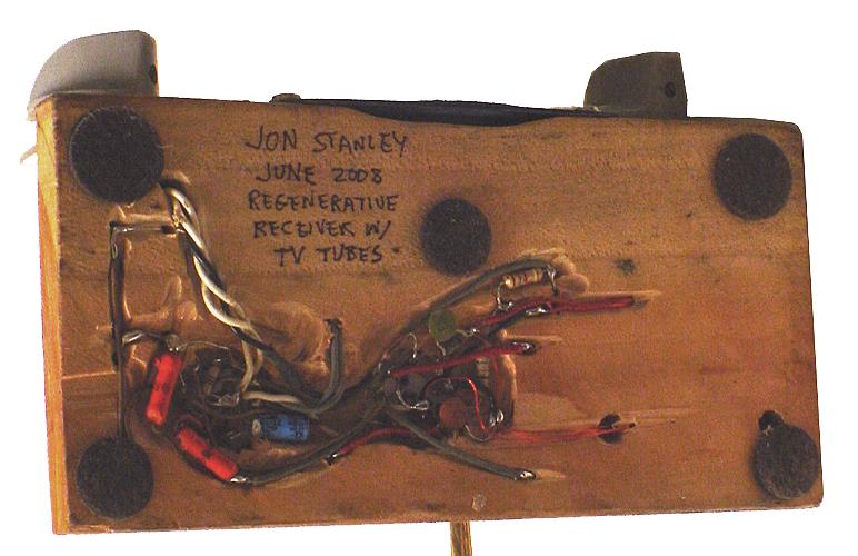
Note that the radio is transformerless and the tube filaments derive their power from 120V mains while in series with a 15uF 250V nonpolarized capacitor. The 15uF capacitor drops about 105 volts at 0.725A at a 60Hz line frequency. Most of the smaller parts such as the 1/4W resistors were stuffed under/inside the wood board. The radio picks up several stations with a short antenna.
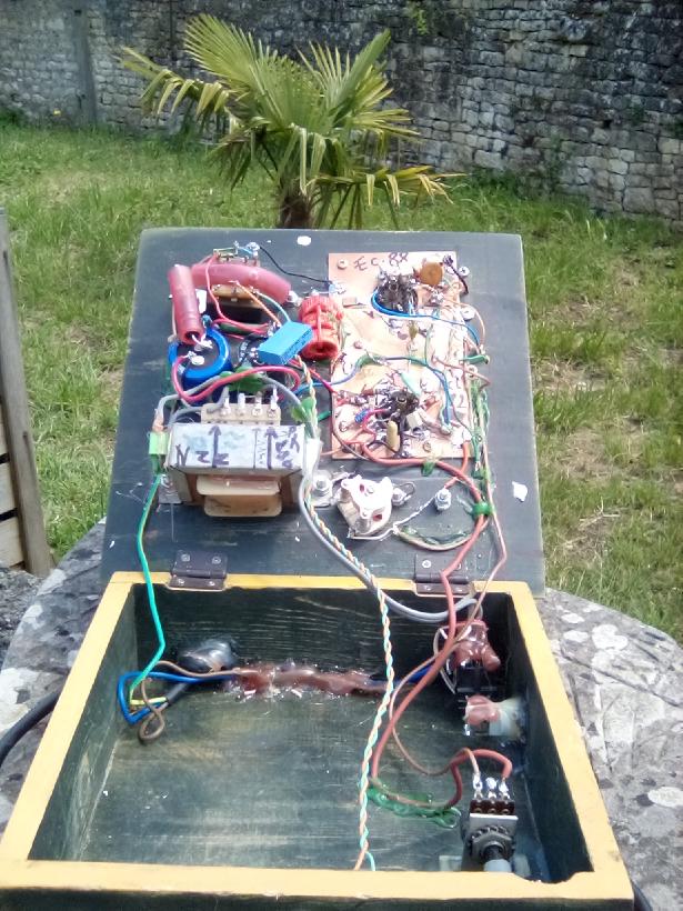
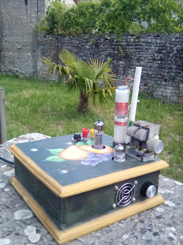
A fellow hobbyist in France replicated this circuit with a different set of tubes and was successful in building a functional regenerative receiver.
Back to Top