Ultra-Simple Oscilloscope
Return to Home
Return to Projects
Solid-State Version
Interested in building one? Buy the Catahoula Technologies Oscilloscope CRT Driver PCB.Simple homemade CRT oscilloscopes are not all that difficult to design and build. I have studied various designs dating back to the thirties and had an interest in developing a simple CRT oscilloscope that the electronics hobbyist could build with readily available parts today. The first oscilloscope I ever built from scratch is the Tube Version shown after this Solid-State version on this webpage. I experimented with some solid-state designs and came up with a design shown in the schematic below.
The schematic design is for a XYZ scope capable of supporting the Dutchtronix scope clock with sharp graphics and also the Version 2 TV-to-Scope converter. The Z axis design is very simple and turns the CRT grid on/off briefly. It works well with the Dutchtronix clock Z axis output and alright with NTSC video. The Z axis circuitry is definitely an area for future improvement.
Before powering up the circuit for the first time, make sure the ASTIG and FOCUS pots are centered, and the INTEN pot rotated all the way towards the negative polarity of the 2.2uF capacitor for maximum brightness. Without any inputs connected, power up the scope and adjust the X and Y position pots until a dot appears in the center of the screen, and then adjust the FOCUS pot until the dot is as sharp as possible and about 1mm in diameter. Afterwards, adjust the ASTIG pot until the dot is as round as possible, and then finally readjust all other controls to your liking.
Transformer Notes
Rather than using voltage doublers directly on the mains supply like my Version 3 XY scope design, I opted to use a power transformer for isolation safety and simplicity. I personally hate power transformers because they are large, heavy, and require special considerations when placed near an electrostatic CRT. I would have opted for a switching power supply but switching supply transformers are not necessarily as straight-forward as a power transformer. This oscilloscope was designed around the Hammond 270X but can tolerate a wide range of transformers that meet the following requirements:
1. 350VCT (175-0-175) to 550VCT (275-0-275) at 40mA minimum
2. 6V at 0.6A minimum
3. 5V at 0.6A minimum
Transformers with higher current capabilities on any one of the three secondaries will work as long as the voltage is close to the required specifications. The primary winding may be chosen to suit the AC mains supply of choice, for instance, 115-120VAC for the USA. The 350VCT secondary is sufficient for the design to operate most 2ö and 3ö CRTs, but likely too low for any 5ö CRTs. A 550VCT secondary is a bit too high for 2ö CRTs, but works nicely for 3ö and some 5ö CRTs.
The 5V winding is used to power the 6.3V CRT filament so it runs a bit dimmer and cooler for longer life. If preferred, the 5V and 6V windings may be swapped so the CRT filament runs at full brightness. The power supplies most likely will still work fine when running off the 5V winding.
CRT Notes
Below is a non-exhaustive list of CRTs that have been tested with this design.
| Type | Size | Works | Color | Notes |
| 2AP1 | 2ö round | Yes | Green | Bright and sharp |
| 3AP1 | 3ö round | No | Green | Requires extensive modification to design |
| 3BP1 | 3ö round | Yes | Green | Bright |
| 3JP1 | 3ö round | Yes | Green | Bright, anode cap connects to B+. |
| 3JP7 | 3ö round | Yes | Blue (yellow afterglow) | Long persistence phosphor version of 3JP1 |
| 3RP1 | 3ö round | Yes | Green | Bright, sensitive deflection |
| 5BP1 | 5ö round | Yes | Green | Dim picture, wonĺt work with TV-to-Scope |
| 5UP1 | 5ö round | Yes | Green | Dim picture, wonĺt work with TV-to-Scope |
| 902A | 2ö round | No | Green | Requires extensive modification to design |
| 913 | 1ö round | No | Green | Requires extensive modification to design |
Some CRTs require an extra connection from the B+ on the PCB to the anode cap, which is detailed further below. Most American CRTs use a straightforward numbering system in which the first digit is the screen size and the number after P is the phosphor type. To list a few common phosphors: P1 is the generic green phosphor, P4 is white, and P7 is long persistence typically used for radar. The long persistence phosphor can create interesting afterglow effects that may be desirable. Below is a phosphor chart with more information on various phosphor types.
Most of the round electrostatic oscilloscope CRTs are difficult to find but are often found new old stock (NOS) from various tube suppliers or ebay. The schematic does not detail a CRT pinout because the design works with several CRTs. The American CRT basing diagrams are shown below.
A table below bridges the signal names in the schematic to the CRT basing diagram.
| Signal Name | Description | American CRT Pin |
| K | Cathode | K |
| A1 | Anode 1 | G3 |
| A2 | Anode 2 | G2,G4,CL ultor |
| G | Control Grid | G1 |
| X1 | Horizontal Deflection 1 | DJ1 |
| X2 | Horizontal Deflection 2 | DJ2 |
| B+ | Anode 3 (if present) | G3,CL post-ultor (anode cap) |
| Y1 | Vertical Deflection 1 | DJ3 |
| Y2 | Vertical Deflection 2 | DJ4 |
If the CRT of choice is not in the American CRT basing diagram then the next best bet is to search through online tube datasheet websites. The diagrams reflect the pins of the CRT base; CRT socket pins are numbered clockwise when viewed from the bottom solder end.
Sockets for older CRTs are difficult to find but makes assembly easier. An alternative is to use individual wires with appropriate pin connectors at the ends. Pin connectors from hard disk drive connectors on PC power supplies work great with most CRT pins.
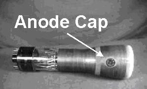
If the CRT comes with an anode cap such as the 3JP1 shown in the picture below then it is possible to make the CRT work by connecting the anode cap to the B+. Do not attempt to solder a wire to the anode cap as that may damage the CRT. Use an appropriate anode cap connector or be creative with a paper clip. Other CRTs may require much higher voltages on the anode cap and cannot be used with this design. However, most preferred electrostatic CRTs do not have the anode cap.
Theory of Operation
The XYZ scope is fairly straight forward. The B+ measures around +350V and is created from full-wave rectification of the 480VCT secondary and filtered with a 10uF capacitor. The negative high voltage needed for the CRT elements are generated by a voltage doubler running off half of the 480VCT secondary to generate about -650V. Note that different transformer selections will lead to significantly different voltages. To provide ballpark figures, a 350VCT transformer will generate B+ of about +245V and a negative HV of -480V. 550VCT will generate B+ of about +390V and negative HV of about -750V. It is important for the B+ to not exceed the 400V ratings of the ZTX458 transistors.
Note that the 5V XYZ scope power supply is capable of supplying enough current for the Dutchtronix clock to operate.
The deflection amplifiers are centered around a differential transistor amplifier that produces equal push-pull voltages on the two deflection plates. The collector voltages on both transistors change at the same amount but in different directions for linear deflection of the beam. A mechanical analogy of the collector voltage behavior is to visualize a seesaw; as collector voltage 1 goes up, collector voltage 2 must go down the same amount. The position pot changes the voltage offset on the amplifier to reposition the beam. The TL082 op-amp circuit is a non-inverting amplifier with high input impedance and adjustable positive gain from 1 to 11. One shortcoming with this circuit is the X and Y inputs cannot exceed the op-amp power supply rails (+/-5V) or the op-amp will saturate and clip the input signal. The op-amp circuit works very well with the Dutchtronix clock to provide a clean and crisp picture. For a general oscilloscope that may need to tolerate input voltages beyond 5V, I would suggest replacing the 100K SIZE pots with a resistor ranging from 10K to 100K to fix the op-amp gain, and then add 1Meg SIZE pots to attenuate the signals as shown in this schematic below.
Oscilloscope
The XYZ scope becomes an oscilloscope with the addition of a sweep circuit, which could be simple or incredibly intricate. The Version 2 TV-to-Scope converter already has two sawtooth sweep circuits for the vertical and horizontal. We only need the horizontal and the speed can be adjusted in ranges by changing the capacitor size. The 555 timer is limited to sweep speeds of up to 500kHz; different components and circuitry would be necessary for faster sweep speeds. Below is a schematic of the sweep circuit to transform the XYZ scope into a simple oscilloscope. The +5V supply for the sweep may be derived from the XYZ scope supplies.
The sweep circuit has basic triggering to synchronize the sweep to the amplified vertical axis signal from the op-amp. Due to the simplicity, the triggering does not always have a perfect lock on certain signals but it does reasonably well for a simple RC circuit.
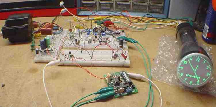
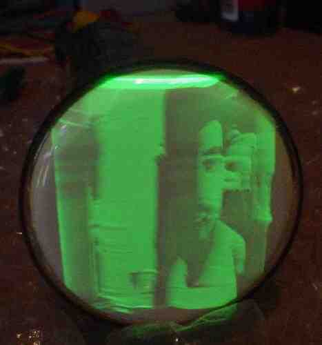
I have not built a pretty stand-alone oscilloscope based on this design to take pictures, but I have some photos of the XYZ scope used with the Dutchtronix clock and TV-to-Scope converter displaying a video feed of me on camera. You've seen an oscilloscope before, right?
Interested in building one? Buy the Catahoula Technologies Oscilloscope CRT Driver PCB.
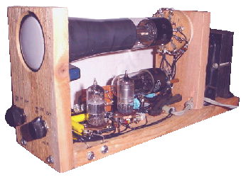
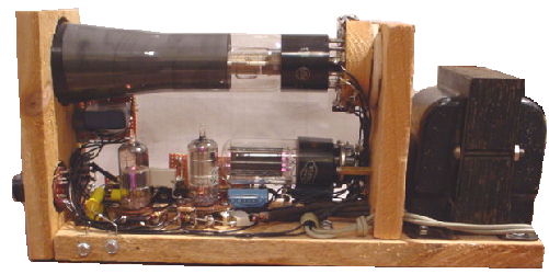
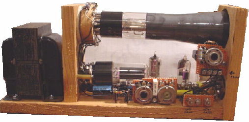
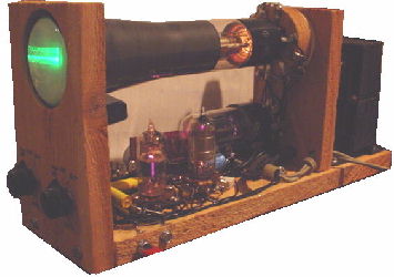
Tube Version
This homemade tube oscilloscope is based on the WaterMan Pocket-Scope 0510A, a 3 tube oscilloscope made in 1946. It is very similar, but slightly simpler than the WaterMan. This oscilloscope is not intended for professional use, but a great learning experience and educational. The frequency range on this oscilloscope is very small and is quite hard to adjust. The waveforms displayed on this oscilloscope are slightly inaccurate, but good enough. Despite all the disadvantages, it does the job for a ultra-simple oscilloscope. I designed another simple transformerless tube oscilloscope years later for use in the scope clock, so be sure to check that out. The tubes used in this ultra-simple oscilloscope are: 5Y3, 6DT6 (or 6AU6), 6J6, and the 2AP1 CRT (the tube used in the WaterMan scope are: 6X4, 6AU6, 6J6, and 2AP1). Below is a schematic diagram of the oscilloscope.
Here is how it works. The 5Y3 is the full-wave rectifier tube that provides about 400VDC.
The 6DT6 tube is used as a vertical amplifier, so the signals fed into VERT INPUT are amplified. The V. GAIN control controls the vertical amplification. Touching your finger on the V. INPUT with the switch on EXT will make a small sine wave, compared to a larger, rough sine wave with the switch on AMP and the V. GAIN turned up.
The 6J6 is a dual triode that is wired uniquely so it oscillates. The capacitors in the RANGE section determine the frequency range the tube oscillates at. The larger capacitor (.33uF) will make the tube oscillate slower, while the smaller capacitor (.001uF) will make it oscillate faster. The smaller the capacitor, the faster the tube will oscillate, allowing you to look at waveforms at higher frequencies. However, there is a point where the oscillations will falter and become screwy. In the RANGE section, one or more of the switches can be turned on, connecting one or more capacitors to the circuit. The 6J6 tube will oscillate its slowest with all the capacitors switched on (when you parallel capacitors, the capacity increases). The FINE FREQ control allows you to change a small amount of the frequency of the 6J6's oscillations. The INT OR EXT HORZ OSC switch allows you to either use the oscilloscope's internal oscillator (6J6) or provide the oscillations through the HORZ INPUT. The H. GAIN serves a similar purpose like the V. GAIN to the horzional oscillator circuit.
Notice the 5Y3's filaments are fed with 6 volts but it is recommended to have a small dropping resistor from 0.8 to 2 ohms to reduce 6 volts to 5 volts.
Also notice the homemade 11-pin tube base for the 2AP1 CRT in the pictures below. I used the pins from two octal tube bases and put them in the holes. The CRT plugs in nicely (it's plugged in half-way on purpose).
The 3.3M ohm resistors from B+ to the vertical and horzional plates of the 2AP1 CRT can be changed out with a 2.2M ohm resistor and a 1M variable resistor in series for centering.
The power transformer should be mounted behind the CRT to prevent distortion or metal shielding around the CRT is recommended.
A Z-intensity connection can be added on this scope. All you need to do is add a .1uF capacitor to the first grid of the CRT, and feed the signals through the capacitor. You also might want to increase the 470K resistor from the brightness control to the first grid.
Some of you might have noticed, there is a flaw in the power supply in the original schematic. The 5Y3's filaments have high B+ voltage, therefore the other tubes' filaments are supplied with that B+ voltage. Those tubes have very low filament to cathode voltage ratings. This will reduce tube life or short them. However, since I have not experienced any negative results, it is better to provide a separate filament supply for the 5Y3 or modify the power supply for a different tube. Below are schematics of two modified power supplies.

This circuit uses a 6X5 rectifier and is strongly recommended. A 6X4 miniature equilavent can be used instead of the 6X5.
This circuit uses a 6SN7 dual triode tube. I currently use this setup since I didn't have a 6X5. This is based on an economical design in the 1930s when designers used a triode tube, usually type-37 as the rectifier. The grid and plate on the 37 were connected. Although the 6SN7 will probably have shorter life, it is easier to replace compared to a 2AP1 CRT.
If you experience lower vertical gain from one of the modified power supplies above, you may replace the 6DT6 with a 6AU6 or similar tubes.