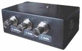
VGA To Scope Converter
Return to Home
Return to Projects
| PIN | PURPOSE |
|---|---|
| 1 | Red video |
| 2 | Green video |
| 3 | Blue video |
| 4 | |
| 5 | Ground |
| 6 | Red ground |
| 7 | Green ground |
| 8 | Blue ground |
| 9 | |
| 10 | Sync ground |
| 11 | |
| 12 | |
| 13 | Horizontal Sync |
| 14 | Vertical Sync |
| 15 |
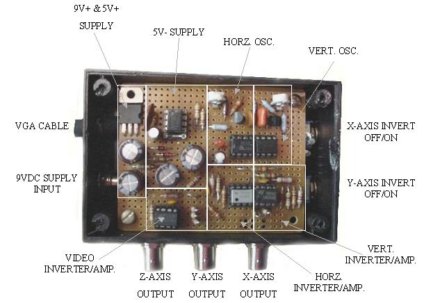
Simply, we take the RGB video signals and combine them into one signal for the Z-axis, and the sync signals are used to trigger the sweep generators. The sweep generators produce sawtooth signals that feed into the X and Y axes of the oscilloscope. Below is a schematic diagram of the VGA-to-scope converter.
NOTE: The sweep generators were built for my PC's VGA specifications, which was 800x600 at 75Hz refresh rate. Different configurations most likely require adjustment of the 3.9K resistor and the 220pF capacitor on the horizontal generator and the 120K and .01uF capacitor on the vertical generator.
The RGB video is converted to monochrome video, which is buffered and inverted by another TL082 for the Z axis. The TL082 could be omitted and an inverted (negative) picture on the oscilloscope is the result.
The power supply generates +9V, +5V, and -5V for the circuits. A 555 timer is used to generate the -5V for the op-amps.
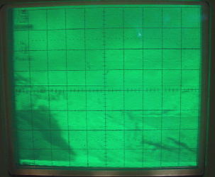
CAUTION: The oscilloscope must have a X, Y, and Z axis, good gain, and X/Y inverters for this converter to be useful. Second, the video MUST be connected before you turn up the brightness of the oscilloscope. Without the video signal connected, the sweep generators are not operating due to the absence of sync signals so a dot appears on the CRT, which can burn the phosphor. Make sure you have a raster before you turn up the brightness. The same goes for shutting down, turn down the brightness of the oscilloscope before you shut down the computer and/or converter.
TRICKS WITH VIDEO: The picture can be flipped by switching between invert and non-invert. The picture can be rotated 90-degrees by swapping the X and Y axes. The oscilloscope X and Y gain will most likely require readjustment to make the picture fit.
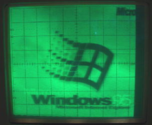
Windows 95 Introduction
Desktop
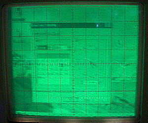
Computer Clock
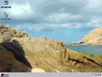
Actual desktop for comparsion
Back to Top