B+ Power Supplies
Table of Contents
1. Disclaimer
2. Introduction
3. The Diode
4. Half-wave rectification
5. Full-wave rectification
6. The Filter
7. The Voltage Divider
8. The Voltage Regulator
9. The Voltage Doubler
10. AC/DC Power Supplies
11. Vibrator Power Supplies
12. Conclusion
Disclaimer
Introduction
The Diode The positive half-wave DC circuit is the most common, used in B supplies. The negative half-wave DC is not often seen, but sometimes used as a negative power supply for the tubes' grids among a few other purposes.
Directly-heated tubes: Tubes without a cathode, the filament acts like the cathode by emitting electrons. Directly-heated tubes are capable of handling more current because the filament is hotter and emits more electrons. One extra note, the filament power in directly-heated tubes must be DC for most circuits because using AC will interfere with the emissions. In radios, directly-heated tubes with AC on the filament will generally make a loud humming noise.
Indirectly-heated tubes: Tubes with a cathode, the filament warms up the cathode so it emits electrons. Indirectly-heated tubes are NOT capable of high currents and are often used in low current power supplies. Indirectly-heated tubes, however, have an advantage of providing isolation between the filament and cathode's electricial circuits. The benefits of this isolation makes it possible to use AC on the filament of most tubes with a cathode.
Ratings of a diode can be changed by means of adding more diodes. Adding more diodes in series increases the voltage rating, and in parallel increases the current rating. For example, two 50V 5A diodes in series has a combined rating of 100V 5A. Using the same example, but in parallel has a combined rating of 50V 10A.
Half-Wave Rectifying
Full-Wave Rectifying
Most vacuum tubes are constructed as a full-wave rectifier designed for the circuit shown above. Typical rectifiers such as 5Y3, 5U4, 6X5, and 80 have two plates and one common cathode (or filament).
The Filter
Unfortunately, when it comes to higher currents and heavier loads, the RC filter is not very efficent. Chokes can be used in place of resistors for more efficent filtering because they have less DC resistance and higher resistances to AC. Below is a diagram of a typical filter system using a choke.
Bleeder Resistors: Resistors that provide a continous load on the filter system. The resistor keeps the electrons flowing from the capacitors in the filter system and also provides a discharge path for the capacitor. Bleeder resistors are ideal for crudely regulating the output voltage of the power supply and prevents voltage surges. Typically they are very high in resistance because they are intended to serve as a very light load. Usual sizes vary from 10K ohm to 450K ohm. The resistor is placed across the output of the filter system from positive to ground. Also, bleeder resistors can be used as a voltage divider, which will be explained next.
The Voltage Divider
The power rating of each resistor can be determined by calculating the power disspated through each resistor using this equation: Power = Volts x Current (P=VI). The power rating is generally a few watts higher than the actual disspated power.
The Voltage Regulator
Most voltage regulator tubes have a jumper that serves as a safety switch. If the regulator tube was removed, the jumper would disconnect the DC supply from the rest of the circuits to prevent the unregulated voltage from causing damage. Below is a diagram of a basic voltage regulator tube circuit. In this example, a 0D3 (VR150) will be used. To calculate the dropping resistor value, lets say the input power is 200V, but 150V regulation is desired. First, look at the maximum current draw of the voltage regulator, in this case, 40mA. The tube is a 150-volt regulator, so the resistor has to drop 200V to 150V. Therefore, the resistor has 50V 40mA across it, and with Ohm's law equals 1,250 ohms. Generally, a 1.5K resistor would suffice.
The regulation voltage can be increased with more voltage regulator tubes in series. For example, two 0D3s (VR150s) can be used in series to regulate the B+ to 300V. Also, paralleling voltage regulator tubes can increase current rating, but current limiting resistors are necessary to ensure that one of the voltage regulators don't fire first and burn out due to a heavier load. The resistor is put in series with the voltage regulator tube, and can be around 50 to 100 ohms.
Another way of regulation uses gas-filled rectifiers. As the load current goes up, the B+ voltage generally drops. However, with a gas-filled rectifier tube, the load current can increase and not affect the B+ voltage. Gas-filled rectifiers are basically a rectifier and voltage regulator in one.
The Voltage Doubler The voltage doubler's output is unfiltered DC and twice the peak voltage of the AC input. In this example, 115V has a peak voltage of 160V, so the output DC voltage is about 320V. The larger the capacitors, more current is provided.
AC/DC Power Supplies As shown above, the triode's grid was connected to plate and the tube serves as a low current rectifier. In many radios, the tube was typically 37.
Vibrator Power Supplies Above is an animation of electron flow in a simple vibrator power supply. Notice the square wave "pseudo" AC on the output of the transformer. There is also another type of vibrator power supply that eliminates the rectifier tube, which uses a synchronous vibrator. Below is a diagram of a synchronous vibrator power supply. Notice how the two reeds switch together synchronously, and specifically picks out the positive DC cycles from the transformer.
Conclusion
This article includes information on the construction of various power supplies that are capable of providing several hundred volts and can KILL! I will not be liable for any accidents. Please DO NOT construct any of the circuits below without any knowledge or experience.
Power supplies are vital in the world of electronics. The most common power source is the household 110V to 120V AC outlet (240V in some other countries). There are several different power supply designs for converting AC to the necessary DC for most electronic circuits. This article presents various vacuum tube power supply designs and some solid-state versions.
A tube with one plate is a diode. A diode only allows electrons to flow in one direction and not the other direction. Because of this, depending on how the diode was installed, the AC's positive or negative cycles would simply be "chopped" off and become zero volts generally. The results are half-wave DC. Below is an example of two ways AC is converted to half-wave DC.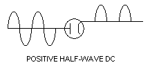
A half-wave B+ power supply generally uses one diode and "chops" off the negative cycles of the AC source. Half-wave DC can be obtained from various AC power sources, including mains (120V), transformers, and flybacks. Below are different circuits that provides half-wave DC.
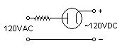
Half-wave B+ from mains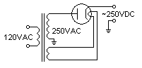
Half-wave B+ from transformer
A full-wave B+ power supply, as opposed to half-wave DC, uses more diodes and uses the inverted AC signals from the AC power source, instead of one. There are two typical ways to obtain full-wave DC; with two diodes and a transformer that has a center tap, or with a bridge rectifier and an AC power source, either mains or with a transformer that has no center tap.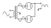
Full-wave DC from transformer with center tap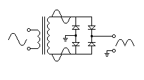
Bridge Rectifier
All the circuits mentioned above are methods of obtaining DC from AC, but they all create pulsating DC. Most circuits, especially communications circuits, need smooth DC and this is where the filter circuits come in. The vital part of most filter systems is the capacitor, which charges up with the pulsating DC and "fills in the gaps" between the pulsating DC cycles. Therefore, the capacitor smoothens out the DC. Below is a simple diagram of the capacitor's actions from the B+ to ground in a simple rectifier circuit.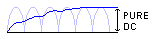


Some particular circuits may need different B+ voltages, especially televisions, which commonly have sophiscated voltage divider circuits. Below is a diagram of a simple voltage divider that provides a 250V 50mA tap and a 100V 40mA tap from a 300V 100mA power source.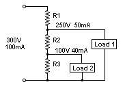
Some power supplies strictly need regulated voltages, such as precision equipment and devices. Voltage swings can alter the accuracy of these devices, either by varying AC voltages or loads. Only the tube-type voltage regulator will be explained in this section. Voltage regulator tubes consists of a plate and cathode in a gas-filled low-pressure environment. The gases react to different voltages, and glows brighter as the conduction increases. Below is a table with information on several voltage regulator tubes.
Tube Type DC Operating Voltage Current Range (mA) 0A2 151 5 - 30 0A3 75 5 - 40 0B2 108 5 - 30 0C3 108 5 - 40 0D3 153 5 - 40 874 90 10 - 50 991 59 0.4 - 2.0 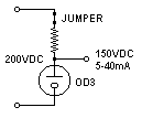
A method of obtaining higher voltages from the AC line is with a voltage doubler. This is one method of eliminating a step-up transformer. Below is a diagram of a voltage doubler using semiconductor diodes. Rectifier tubes can be used in place of the diodes.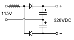
The AC/DC power supply is basically an half-wave rectifier that ran off mains (120V). Many old radios have AC/DC power supplies to eliminate the need of a large, heavy transformer. Some areas only had a DC source, so this circuit was basically "universal." However, a polarized plug would be good, otherwise if the device didn't work on a DC source, the plug had to be reversed. AC/DC power supplies have disadvantages, such as low voltage output. AC/DC radios were popular during the Depression Era for economical reasons. However, many AC/DC radios made during the Depression had a triode instead of an ordinary rectifier. Below is a diagram of a modified half-wave B+ power supply using a triode.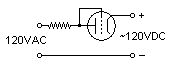
Back in the days before the transistor was invented, vibrators and a step-up transformer were used to increase the voltage from batteries. The vibrator is basically a high frequency switch that oscillated the battery's power into the primary of the transformer and generated "pseudo AC." Below is a diagram of a simple vibrator power supply.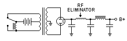
Although most of the power supply circuits on this page are relatively outdated, they still show the same basic concepts that our modern solid-state devices have replaced. Many power supplies today still use the same circuits as those in the mid-50s.
Back to Top