My Crystal Radio Page
Site Navigation
Back to my old radio page!
Back to my main page!
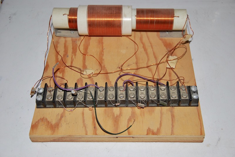
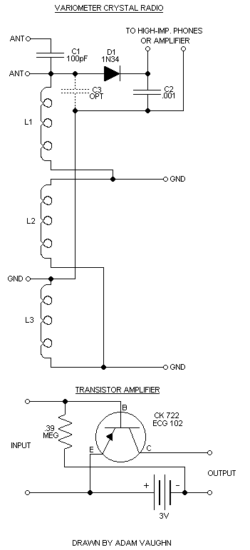
Lately, I've been building crystal radios like the early radio pioneers used. Crystal radios require no outside sources of power to operate, just the radio waves themselves. The first crystal set I built was a "variometer" radio. In this design, one larger coil slides over a smaller coil to change the coil's inductance, eliminating the need for a variable capacitor. The radio I'm building has two smaller coils, making it more selective (?). I got the design from the May 1995 issue of Popular Electronics. The coil forms are made from PVC pipe. The smaller, longer coil which holds the two smaller coils is 8 inches long and 1 inch inside diameter. The shorter, larger coil which slides over the other pipe is 3 inches long and 1.5 inches inside diameter. The other components are installed using a long terminal strip. At first the radio didn't work because the detector diode, which should be a 1N34 germanium diode, was a Zener diode. Luckily, someone sent me some 1N34A germanium diodes, and now it works fine. Since I live in a "fringe" area for AM signals and my only set of high-impedance headphones has an intermittent connection in the "junction box" where the headphone cord is split to the two 'phones, I've added an onboard one-transistor amplifier, whose design I found in the Boys Second Book of Radio and Electronics. Unfortunately, it has some problems. When using a crystal earphone as a microphone, the output is soft and unintelligible. The problem could lie with the transistor, since I'm using a 2N217 (ECG102A) when the original circuit calls for a CK722 (ECG102). The ECG102A is a more rugged version of the ECG102, but the voltages are different. Reducing the bias(?) resistor from .39 Meg to 27K and doubling the voltage from 3V to 6V hasn't made a difference. A photo and schematic of both can be found below.
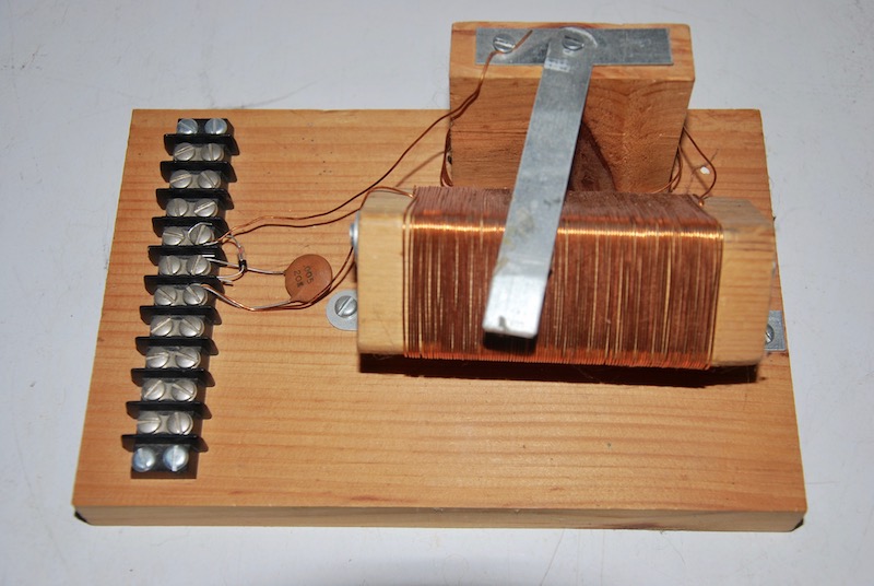
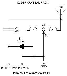
My second crystal radio is a much-simpler "slider" set. This type of crystal set uses a single coil and a "slider," which is a piece of metal which slides over the tuning coil to tune the radio. Like my other crystal set, all the parts are mounted on a terminal strip. Unlike my other crystal set, this one uses a square wooden coil form mounted diagonally. I found the design for this set in The Boys First Book of Radio and Electronics. This radio worked on the first try. This surprised me since the coil, which called for 130 feet of 26-gauge wire, has roughly 51 feet of 22-gauge wire (I had no 26-gauge wire so I used what I had, which was 22-gauge wire). This crystal set isn't quite as selective as it could be, but it works just as well as my variometer crystal set (possibly better). A photo and schematic of this set can be found below.
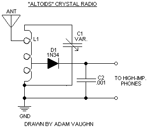
My third crystal radio project is a simple ferrite coil and variable capacitor design. I was originally planning to build this radio in an "Altoids" mints tin. I salvaged the coil and variable capacitor from a failed AM/FM radio kit I once tried to build. The FM section, which came on a prebuilt circuit board, would tune from what I believe is below the FM broadcast band to the very beginning of it, while the AM section, which didn't even have a detector diode, would only get one station, with the tuning capacitor only varying the volume of the station. Instead of the 2SC transistor-based "preamplifier" the AM section of the AM/FM radio kit used, which I suspect is what caused the tuning problem, I'm going to be using a true detector diode. I was hoping the metal tin wouldn't cause problems with the antenna coil. Unfortunately, mounting the ferrite coil in the tin seemed to be causing the coil to act like a wavetrap, blocking AM signals and only allowing shortwave signals (I was surprised to hear CBC and BBC World Service drifting in and out of my headphones). Also, the variable cap did nothing, and it got two or more signals at once. I transplanted the innards to a Radio Shack plastic enclosure, hoping it would fix the problem, but it didn't change. I may have to redesign the circuit. A schematic of this set can be found below.
The fourth crystal radio project is a short-range FM crystal set. This is the most complex crystal set I've built to date. No easy-to-work-with wooden boards or small plastic enclosures involved; just a small tuning capacitor, a 12" piece of #10 copper wire (for the coil), a diode and a capacitor. I mounted all the parts on the tuning capacitor, including the coil (which was extremely difficult to attach). I bought the parts as a kit from the late Bill Turner. I haven't tried it out yet. A schematic can be found here.
So far I've built three crystal sets and I'm in the process of building another. All I need is a better pair of headphones and possibly a better antenna (my current antenna is a 100 foot long wire strung between two trees) and/or ground (currently I use a baseboard heater). More later!
Other crystal radio pages
The Xtal Set Society
Crystal Radio Resources